Correction table creation method for head position control, head position control method and disk device
a correction table and head position technology, applied in the direction of data recording, track finding/aligning, instruments, etc., can solve the problems of deteriorating positioning accuracy, difficult measurement and correction, and inability to accurately record servo signals concentrically during stw, so as to achieve the effect of reducing the rro after correction
- Summary
- Abstract
- Description
- Claims
- Application Information
AI Technical Summary
Benefits of technology
Problems solved by technology
Method used
Image
Examples
first embodiment
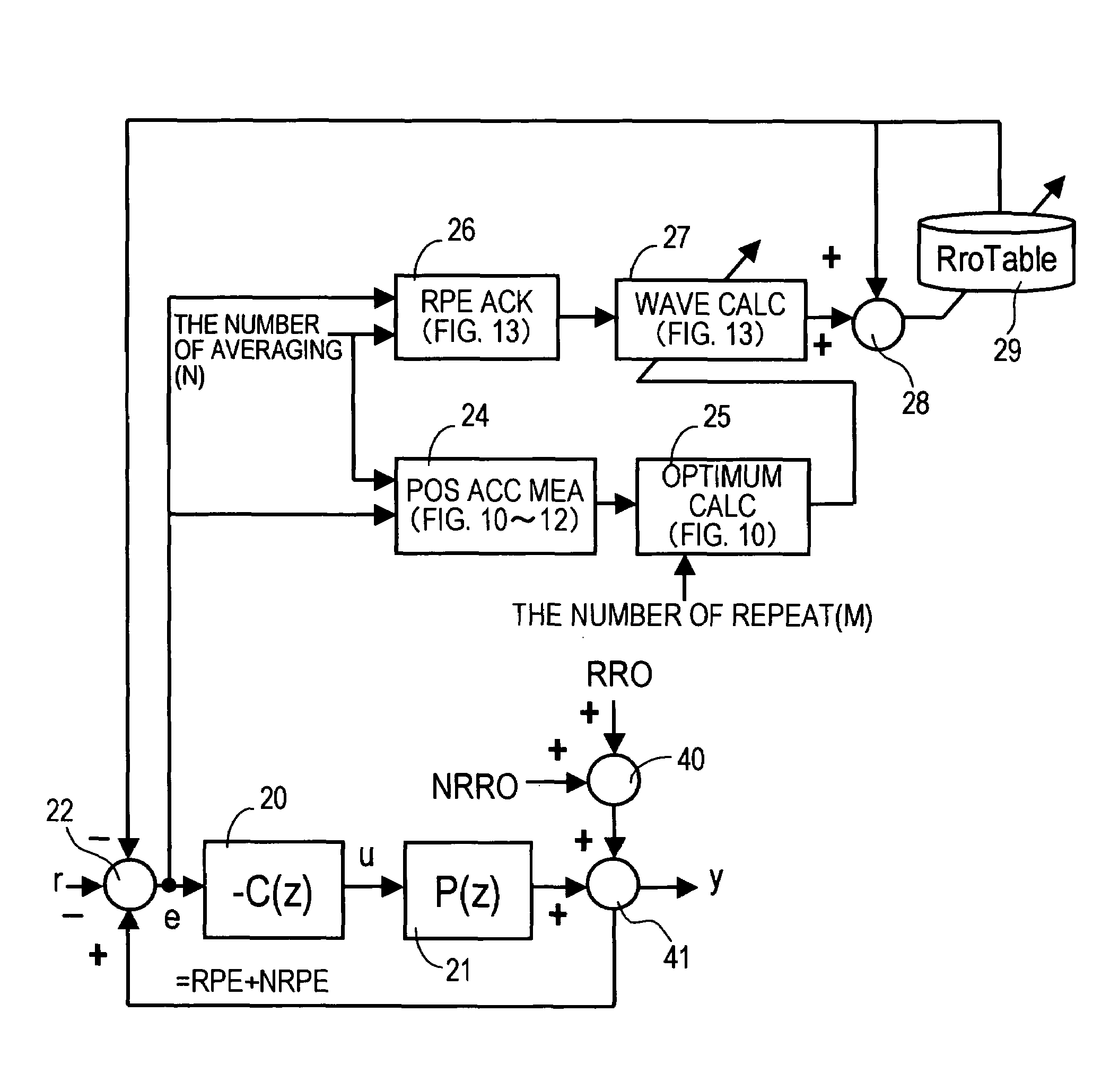
[0125]FIG. 7 is a block diagram depicting the head positioning control system of the present invention, FIG. 8 is a flow chart depicting the manufacturing steps of the disk device of the present invention, FIG. 9 is a diagram depicting the residual RRO for creating RroTable, FIG. 10 is a flow chart depicting the RRO gain optimum value calculation processing using the residual RRO in FIG. 9, FIG. 11 is a flow chart depicting the RRO measurement processing, and FIG. 12 is a flow chart depicting the NRRO measurement processing in FIG. 10.
[0126]FIG. 7 is a block diagram for the case when the optimum value calculation and the correction table creation are performed on a single disk device unit, and composing elements the same as those in FIG. 6 are denoted with the same reference numerals. In other words, the error ‘e’ between the target position ‘r’ and the current (observing) position ‘y’ is determined by the computation block 22, the controller 20 performs control computation, calcula...
second embodiment
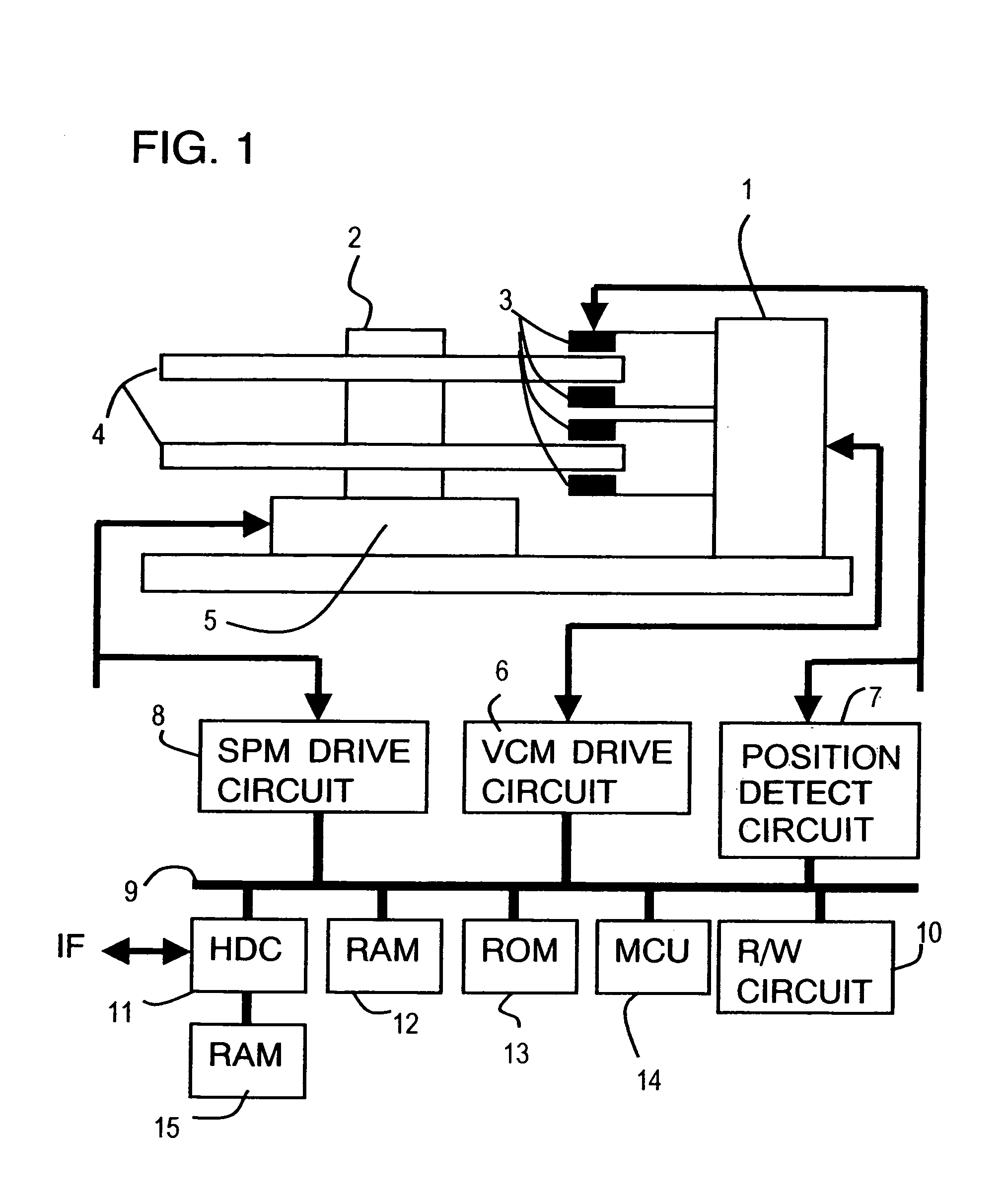
[0194]FIG. 19 is a block diagram depicting the RRO correction table creation system according to the present invention. In FIG. 19, composing elements the same as FIG. 7 are denoted with the same reference numerals, and the difference from FIG. 7 is that the optimum gain calculation processing 25 (FIG. 10) is executed by an external device (e.g. personal computer) 50 connected to the disk device, and the result is set in the gain table 30 in the disk device.
[0195]If this configuration is used, the addition gain is calculated using the external device 50, so the load of the MCU 14 in the disk device can be decreased, and the addition gain can be calculated at high-speed.
third embodiment
[0196]FIG. 20 is a block diagram depicting the RRO correction table creation system according to the present invention. In FIG. 20, composing elements the same as FIG. 7 are denoted with the same reference numerals, and the difference from FIG. 7 is that the positioning accuracy measurement processing 24, the optimum gain calculation processing 25 (FIG. 10–FIG. 12), the RPE acquisition processing 26 (FIG. 13), and the waveform calculation processing 27 (FIG. 13) are executed by an external device (e.g. personal computer) 50 connected to the disk device, and the result is set in the RRO correction table 29 in the disk device.
[0197]When this configuration is used, the table values of the RRO correction table 29 are calculated, so the load of the MCU 14 of the disk device can be decreased further, and the table values can be calculated at high-speed. Also the correction table creation processing program is unnecessary in the disk device after shipment of the disk device, so the time re...
PUM
| Property | Measurement | Unit |
|---|---|---|
| rotation | aaaaa | aaaaa |
| sampling frequency | aaaaa | aaaaa |
| current | aaaaa | aaaaa |
Abstract
Description
Claims
Application Information
 - R&D
- Intellectual Property
- Life Sciences
- Materials
- Tech Scout
- Unparalleled Data Quality
- Higher Quality Content
- 60% Fewer Hallucinations
Browse by: Latest US Patents, China's latest patents, Technical Efficacy Thesaurus, Application Domain, Technology Topic, Popular Technical Reports.
© 2025 PatSnap. All rights reserved.Legal|Privacy policy|Modern Slavery Act Transparency Statement|Sitemap|About US| Contact US: help@patsnap.com


