
Method and apparatus for reducing effective track width through highly skewed head angles

Inactive Publication Date: 2007-03-20
MAXTOR
View PDF13 Cites 27 Cited by
  • Summary
  • Abstract
  • Description
  • Claims
  • Application Information

AI Technical Summary

Benefits of technology

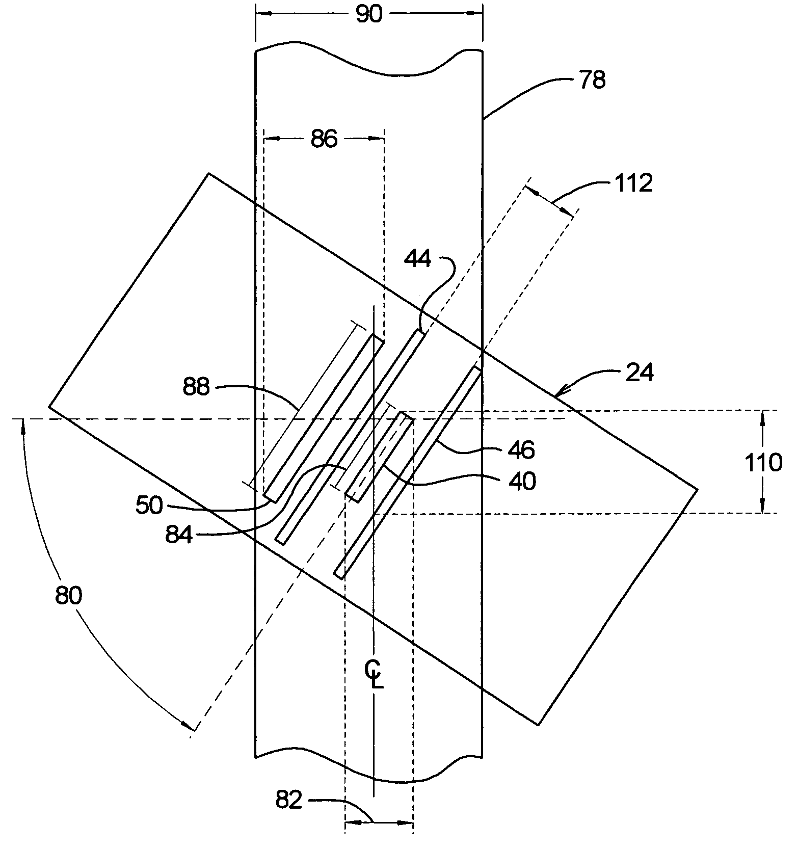
[0029]The present invention solves the aforementioned problems and meets the aforementioned, and other, needs. The present invention provides a disk drive which employs a head with a high skew angle. This allows the head width to increase according to the inverse of the cosine of the head skew ang

Problems solved by technology

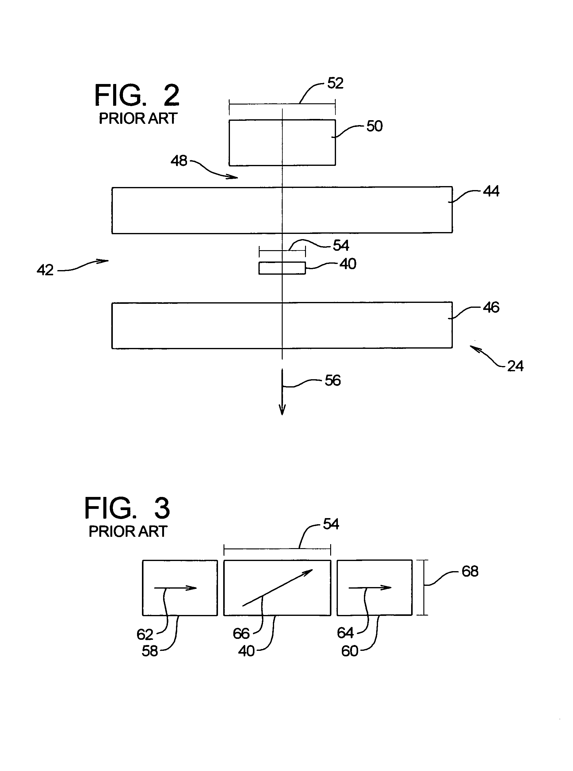
However, due to limitations in the manufacturing technology used to fabricate heads, it is becoming increasingly difficult to manufacture heads with read and write elements that have the required width.
Thus, it is often particularly difficult to fabricate the read element with the appropriate width.
However, current photolithographic limits in the fabrication process are roughly the same as the nominal width of the read element.
Operating this close to the limits of the fabrication process can often result in heads which do not meet the nominal width and tolerance requirements.
This can be expensive due to the time to measure the heads as well as the cost of unusable heads.
As a result of the reduced track width, and the resulting decrease in the read element width, the aspect ratio of the read element increases which in turn degrades the analog read signal.
Furthermore, while an MR read element has been described, similar problems are encountered with GMR read elements.
Another difficulty that arises from reduced track width is reduced magnetic flux from the magnetic transitions on the disk.
Such a change in fly height, in general, is not desirable.
If the head 24 has a relatively high skew angle, it may be difficult to write a radially coherent servo pattern, resulting in a much longer servo write process.

Method used


Image

  • Method and apparatus for reducing effective track width through highly skewed head angles
  • Method and apparatus for reducing effective track width through highly skewed head angles
  • Method and apparatus for reducing effective track width through highly skewed head angles

Examples


Embodiment Construction

[0040]While this invention is susceptible of embodiments in many different forms, there are shown in the drawings and will herein be described in detail, preferred embodiments of the invention with the understanding that the present disclosure is to be considered as an exemplification of the principles of the invention and is not intended to limit the broad aspects of the invention to the embodiments illustrated.

[0041]Referring to FIG. 5, a diagrammatic illustration of the head 24 in relation to a track 78 on the disk 12 in accordance with an embodiment of the present invention is now described. In this embodiment, the head 24 has a high skew angle 80 with respect to the track 78. The high skew angle 80 results in the read element 40 and the write element 50 being highly skewed with respect to the track 78. The high skew angle 80 also results in the read element 40 having an effective width 82 with respect to the track 78 which is narrower than a physical width 84 (width 54) of the ...


PUM


Abstract

A disk drive provides increased read and write element widths and tolerances, and also provides reduced track widths. The head with the read and write elements has a large skew angle relative to the tracks on the disk. The skew angle reduces the effective width of the read and write elements. Based on this reduction in effective width, the physical width of the read and write elements may be increased. Furthermore, the width of the tracks may be reduced instead of, or in addition to, the increased read and write element width.

Description

[0001]This application claims priority from U.S. Provisional Application Ser. No. 60 / 232,810, filed Sep. 15, 2000 entitled “Reducing Effective Track Width Through Highly Skewed Head Angles,” which is incorporated by reference in its entirety.FIELD OF THE INVENTION[0002]The present invention relates to magnetic storage devices, and, more particularly, to increasing track density on a magnetic storage medium and increasing head width tolerance.BACKGROUND OF THE INVENTION[0003]A diagrammatic representation of a conventional disk drive 10 is illustrated in FIG. 1. The disk drive 10 includes a disk 12 that is rotated by a spindle motor 14. Digital information is stored within concentric tracks on the disk 12 which is coated with a magnetic material that is capable of changing its magnetic orientation in response to an applied magnetic field. The spindle motor 14 is mounted on a base plate 16. An actuator arm assembly 18 is also mounted on the base plate 16. The disk drive 10 also include...

Claims


Application Information

Patent Timeline
IPC IPC(8): G11B5/00G11B20/20G11B5/596
CPCG11B5/4826G11B5/59655G11B5/4886G11B5/4833
Inventor LIIKANEN, BRUCEPURKETT, JOHN C.KEEFER, TERRY
Owner MAXTOR
Learn More