
Architectural covering

a technology for buildings and coverings, applied in the direction of door/window protective devices, curtain suspension devices, shutters/movable grilles, etc., can solve the problems of separating the two layers, blinds not being able to completely close, blinds appearing bulky,

Inactive Publication Date: 2007-03-20
HUNTER DOUGLAS IND BV
View PDF25 Cites 15 Cited by
  • Summary
  • Abstract
  • Description
  • Claims
  • Application Information

AI Technical Summary

Benefits of technology

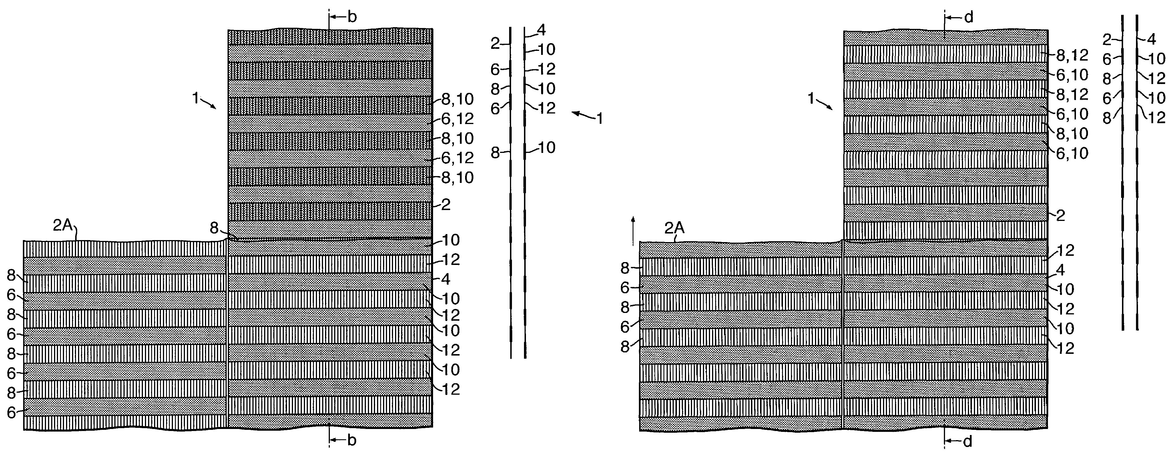
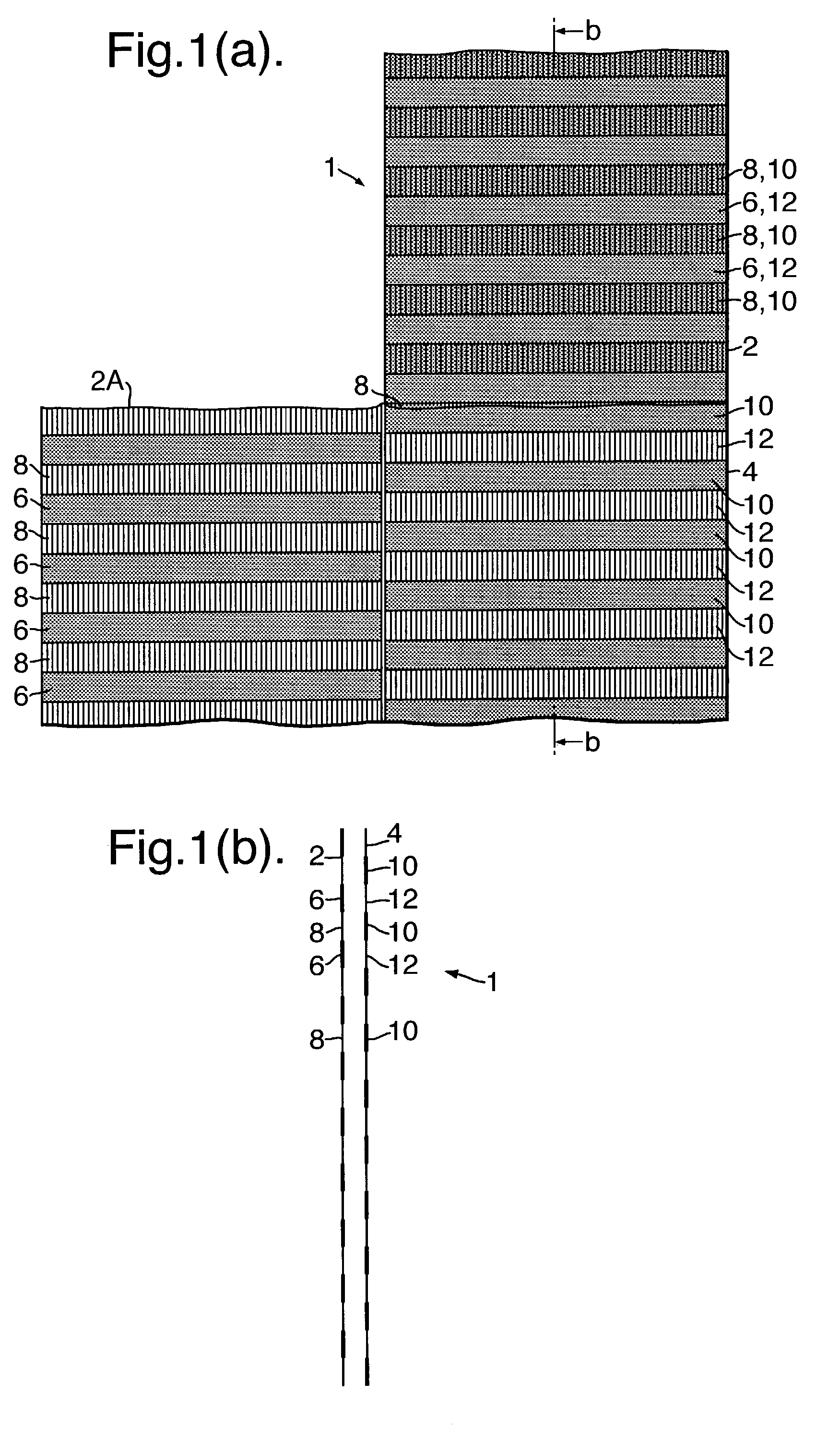
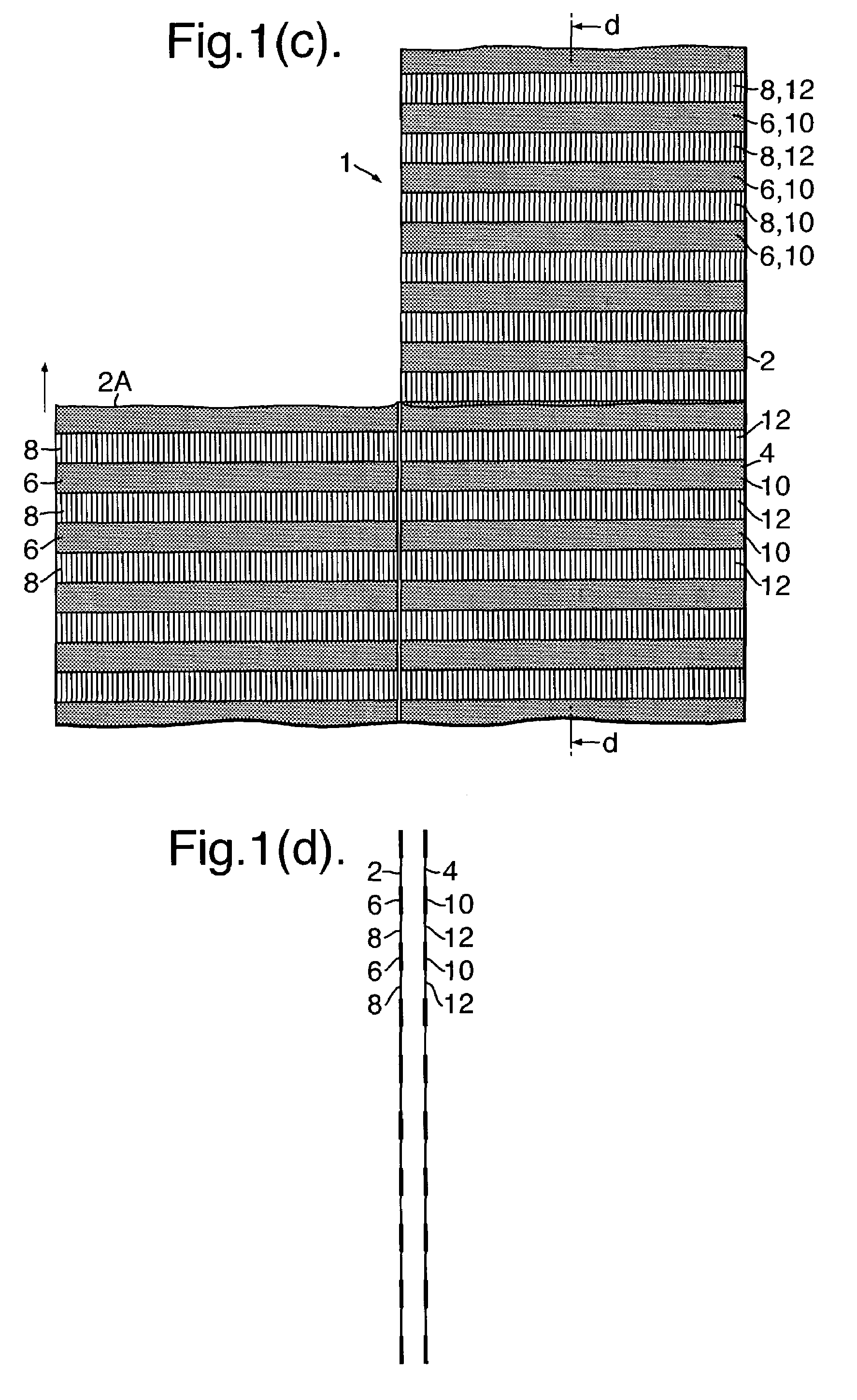
[0013]the first and second layers having complementary patterns.By this invention, the two layers of the covering can be kept close together at all times, even when the second layer is moved relative to the first layer along the binder thread between positions where the patterns of the layers either complement each other or do not complement each other. In this regard, the covering need not have any significant gap between its two layers and need not be bulky but rather can have almost the appearance of a single layer of material.
[0025]It is yet further advantageous that each binder thread and any pulling thread in the coverings, described above, is a preshrunk and smooth thread, especially where the layers of the covering are not preshrunk, particularly where the covering is eventually subjected to heat shrinkage, whereby when the covering eventually shrinks during heating, each binder thread and each pulling thread will become looser within the covering.

Problems solved by technology

This generally results in the layers being separated by the diameter of the bars used, which makes the blind appear bulky.
Also the distance, separating the two layers, does not allow the blind to completely block light from passing through it.
Moreover since the layers in such a blind are connected only at their top and / or bottom, precisely aligning their transparent and opaque stripes to completely close the blind is not possible.
However, the two layers of such a fabric cannot slide along the binder threads or move relative to one other.

Method used


Image

  • Architectural covering
  • Architectural covering
  • Architectural covering

Examples


second embodiment

[0046]FIGS. 2(a) and (b) show a fabric blind 101 which is similar to the blind 1 of FIGS. 1(a)–(d) and for which corresponding reference numerals (greater by 100) are used below for describing the same parts or corresponding parts. The relatively opaque stripes 106 of the front layer 102 of the blind 101 can be horizontally aligned with the relatively translucent stripes 112 of its rear layer 104 to close the blind as shown in FIG. 2(a) and can be horizontally aligned with the opaque stripes 110 of its rear layer 104 to open the blind as shown in FIG. 2(b). This fabric blind 101, when closed, can easily be printed on both the opaque stripes 106 and the weft threads of the translucent stripes 108 of its front layer 102, as well as on the opaque stripes 110 of its rear layer 104 (between the weft threads of the translucent stripes 108 of the front layer), by conventional transfer printing techniques. Thereby, the closed blind 101 will show the complete printed design, and the opened b...

third embodiment

[0055]FIGS. 4(a)–(c) show a fabric blind 201 which is similar to the blind 1 of FIGS. 1(a)–(d) and for which corresponding reference numerals (greater by 200) are used below for describing the same parts or corresponding parts. In this regard, the stripes 206A, 208A, 210A, 212A at the bottom of the blind 201 are vertically narrow, and the stripes 206B, 208B, 210B, 212B at the top of the blind are vertically wide. The opaque stripes 206A, 206B of the front layer 202 of the blind 201 can be horizontally aligned with the translucent stripes 212A, 212B of its rear layer 204 to close the blind as shown in FIG. 4(a) and can be horizontally aligned with the opaque stripes 210A, 2101B of its rear layer 204 to open the blind as shown in FIG. 4(b). As shown in FIG. 4(c), the narrow opaque stripes 206A of the bottom of the front layer 202 can be aligned with the narrow translucent stripes 212A of the bottom of its rear layer 204 to close the bottom of the blind while the wide opaque stripes 20...

fourth embodiment

[0063]Shown in FIG. 7 is a fabric blind 301 which is similar to the fabric blind 1 shown in FIGS. 1(a)–(d), 3(a)–(b), 5 and 6(a) and for which corresponding reference numerals (greater by 300) are used below for describing the same parts or corresponding parts. The blind 301 is woven, starting with a complete set of warp and weft threads 320 and 322, forming front and rear, opaque stripes (not shown) and front and rear, translucent stripes (not shown). The warp threads 320 are divided into front and rear sub-sets 320a, 320b, with a width and height measured in the weft direction, and by weaving these warp thread sub-sets with front and rear, weft thread sub-sets 322a and 322b, the front and rear layers 302, 304 are formed. One or more binder threads 314 are woven, as extra weft threads 322, into front and rear, warp thread sub-sets 322a and 322b which form the opaque stripes of the front and rear, woven layers 302, 304 of the fabric 301, in order to slidably interconnect the layers....


PUM

PropertyMeasurementUnit
Electrical resistanceaaaaaaaaaa
Translucencyaaaaaaaaaa
Opacityaaaaaaaaaa

Abstract

A covering for an architectural opening, having a first layer with alternating relatively opaque stripes and relatively translucent stripes, and a second layer with alternating relatively opaque stripes and relatively translucent stripes. The first and second layers are positioned one behind the other, with the stripes substantially parallel. The first and second layers are movable relative to one another in a direction substantially perpendicular to the stripes. The covering also includes a series of parallel binder threads for attaching the first layer to the second layer. The binder threads run substantially perpendicular to the stripes, and thereby, one of the layers can be slid along the binder threads when moved relative to the other. The blind is preferred to be woven as a double-layer fabric.

Description

CROSS-REFERENCE TO RELATED APPLICATIONS[0001]This application is a continuation of U.S. nonprovisional patent application Ser. No. 09 / 676,069 entitled, “Architectural Covering,” filed 29 Sep. 2000, now U.S. Pat. No. 6,582,794 which claims priority to European application no. 99203208.6, filed 1, Oct. 1999, and to European application no. 00202325.7, filed 4 Jul. 2000. The '069 application and the two European priority applications are hereby incorporated by reference as though fully set forth herein.BACKGROUND OF THE INVENTION[0002]1. Field of the Invention[0003]The invention relates to an architectural covering, particularly a covering for an architectural opening such as a window blind, having two parallel interconnected fabric layers which contain complementary patterns and can be moved relative to one another in a direction parallel to the layers. This invention particularly relates to an architectural covering having one or more parallel binder threads which connect the fabric ...

Claims


Application Information

Patent Timeline
IPC IPC(8): A47H5/00D03D11/00E06B9/24
CPCD03D11/00E06B9/24Y10T428/24025Y10S160/07E06B2009/2452Y10T442/488Y10T442/3472Y10T442/659Y10T428/249923
Inventor FRANSEN, ANTON PETRUS THEODORUS HUBERTUS
Owner HUNTER DOUGLAS IND BV
Learn More