
Laser measurement system

a laser measurement and laser technology, applied in wave based measurement systems, instruments, reradiation, etc., can solve the problems of large device technology cost, spatial deflection of measuring beams that require considerable device technology, and complex mechanical structure of deflection units, so as to reduce the number of data points, avoid diffuse reflection, and increase the data density in the area of interest

Inactive Publication Date: 2007-03-13
ZOLLER & FROEHLICH GMBH & CO KG
View PDF29 Cites 88 Cited by
  • Summary
  • Abstract
  • Description
  • Claims
  • Application Information

AI Technical Summary

Benefits of technology

The invention is a measurement system that includes a rotating mirror and a pivoting measuring head for scanning three-dimensional objects. The mirror is mounted in a rotary head that can rotate about a perpendicular axis. The system can scan a full circle of the mirror during one rotation, allowing for continuous scanning in columns. This is easier to control than other solutions that require reciprocation of the mirror. The system also includes a rotating exit window to minimize reflections and a simple mount design for the measuring head. The technical effects of the invention include improved data density and flexibility in controlling data density in different areas of interest.

Problems solved by technology

Owing to the multiplicity of moved elements (cam follower wheel, counterweights, toothed rack, gear), such a deflection unit has a very complex mechanical structure with a great mass.
An additional drawback resides in that the visual range is restricted in the vertical direction.
In this variant, too, considerable expense in terms of device technology is necessary for spatial deflection of the measuring beam.

Method used


Image

  • Laser measurement system
  • Laser measurement system
  • Laser measurement system

Examples


Embodiment Construction

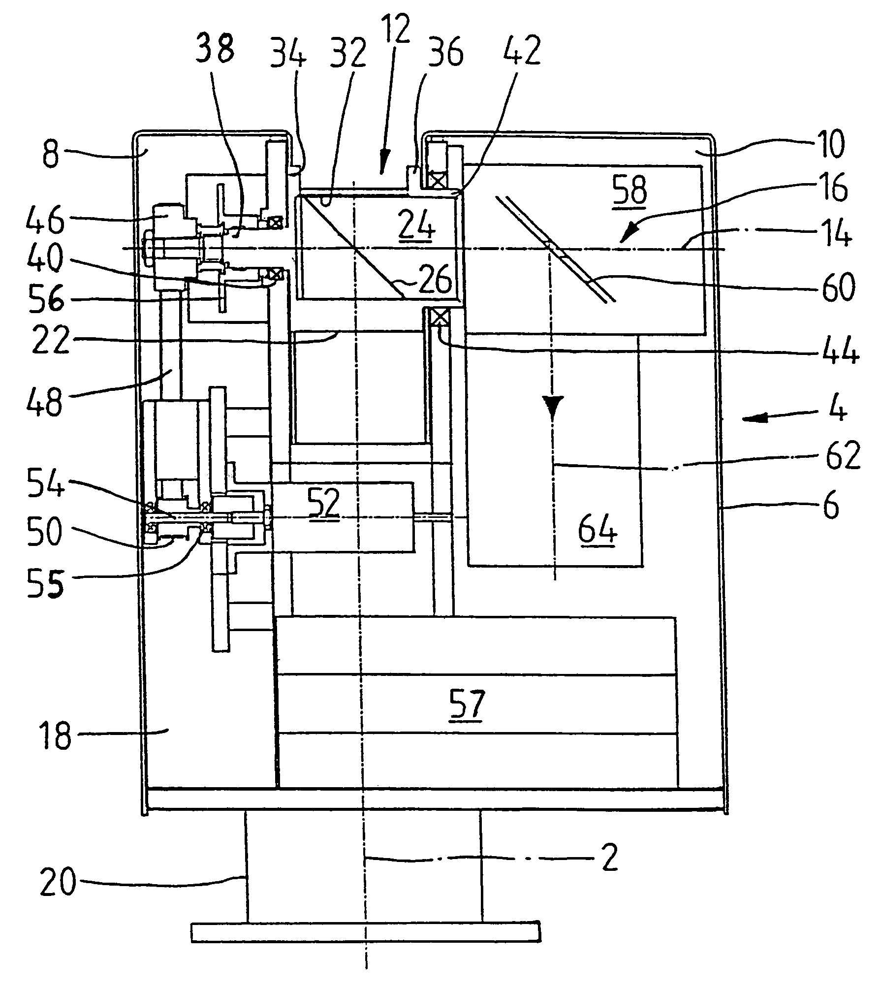
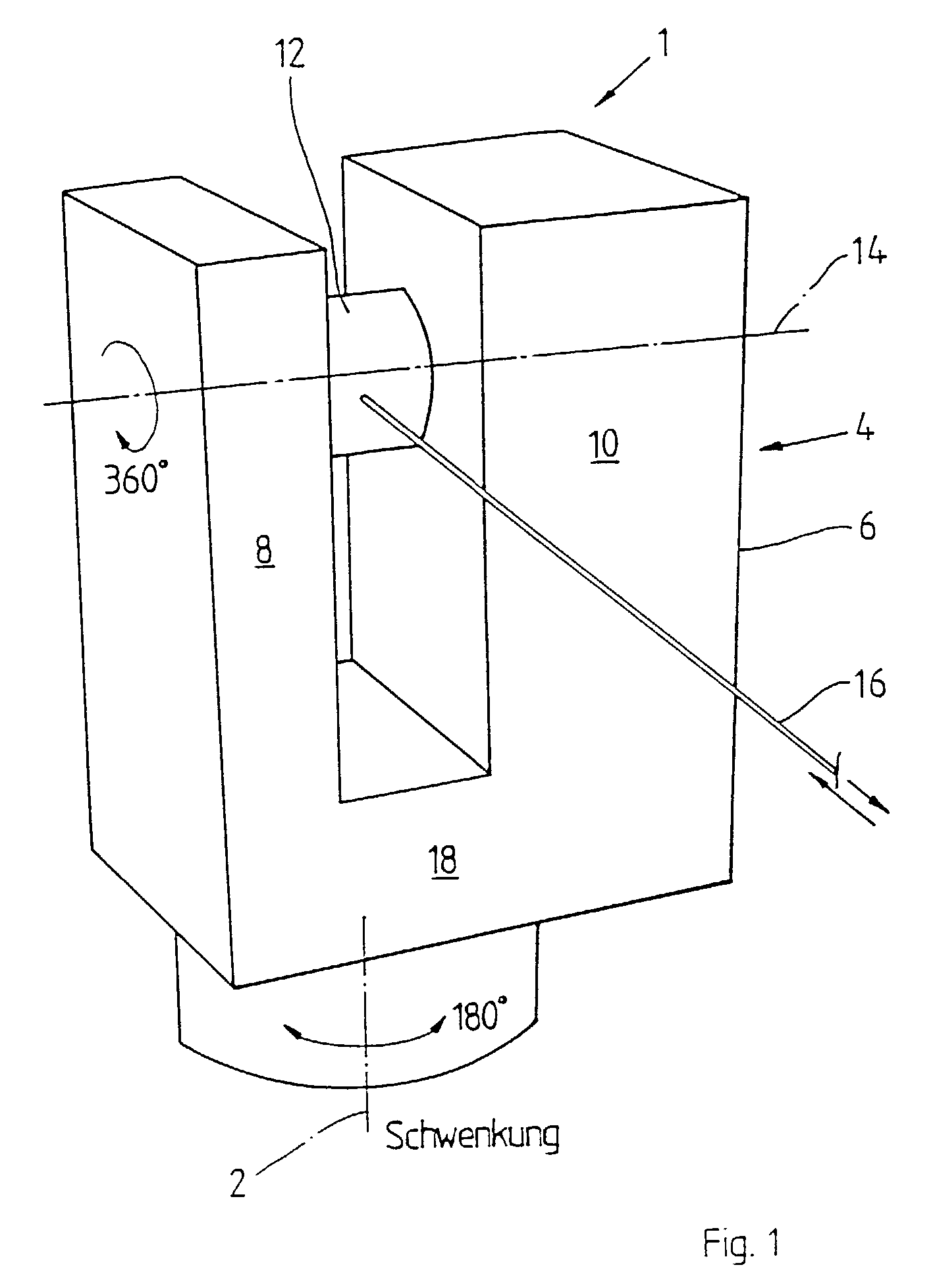
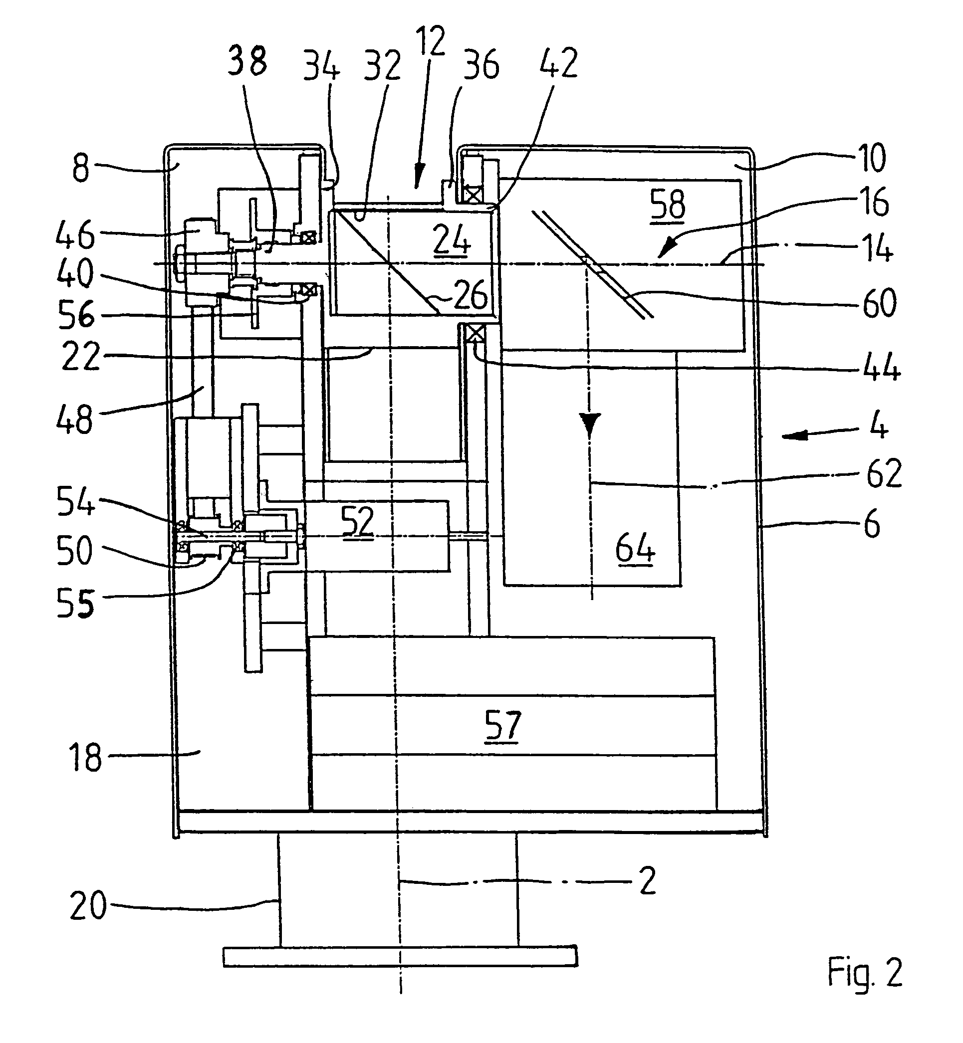
[0018]FIG. 1 is a schematic representation of a 3-D laser measurement system including a measuring head 4 that is pivotable about a vertical rotation axis 2. This measuring head comprises a housing 6 with two support legs 8, 10 having mounted therein a rotary head 12 which is continuously rotatable about a rotation axis 14 having a horizontal orientation in the representation according to FIG. 1. The rotary head 12 furthermore includes an optical system—to be described more closely in the following—through which a laser measuring beam may be directed at an object.

[0019]As a result of the rotatable mount of the rotary head 12, this measuring beam 16 rotates about the rotation axis 14, so that in effect a vertical plane is scanned. The laser light reflected by the object is then admitted through the rotary head 12, deflected, and evaluated by an evaluation unit including an optical receiver, wherein it is possible to deduct the propagation delay of the laser light and thus the distanc...


PUM


Abstract

What is disclosed is a 3-D laser measurement system, including a mirror continuously rotatable about a rotation axis which extends, e.g., in parallel or coaxial with a measuring beam emitted by an optical emitter and impinging on the mirror.

Description

FIELD OF THE INVENTION[0001]The preferred embodiment is directed to laser measurement systems and more particularly, a 3-D laser measurement system employing an efficiently designed deflection mechanism.DESCRIPTION OF RELATED ART[0002]In a like measurement system, the laser measuring beam emitted by an optical emitter is deflected by a mechanical beam deflection system in such a way that full-surface, three-dimensional spatial scanning or measurement of a surrounding is made possible. The digitized measurement data is stored on a computer system, to there be available for further processing and for visualization of the object under measurement.[0003]3-D measurement is carried out by passing the modulated laser light across the environment to be measured, wherein point measurement of both the distance and reflectivity values is possible for different directions in space. Distance and reflectivity images result from the organization of all measured directions in space. The distance im...

Claims


Application Information

Patent Timeline
Patent Type & Authority Patents(United States)
IPC IPC(8): G01D11/24G01B11/03G01B11/24G01C15/00G01S7/48G01S7/481G01S17/89
CPCG01C15/002G01S17/89G01S7/4817G01S7/4811
Inventor FROEHLICH, CHRISTOPHMETTENLEITER, MARKUSZEBANDT, MARTIN
Owner ZOLLER & FROEHLICH GMBH & CO KG
Learn More