
Deck screws suitable for use with composite lumber

a composite lumber and screw technology, applied in the field of screw, can solve the problems of pressure-treated yellow pine deck surfaces that tend to crack, split, twist and splinter, property owners are confronted with the considerable expense of replacing deck boards, money and labor, etc., and achieve the effect of reducing, if not eliminating, the number of instances of volcanoing or mushrooming

Inactive Publication Date: 2007-03-13
OMG INC
View PDF43 Cites 17 Cited by
  • Summary
  • Abstract
  • Description
  • Claims
  • Application Information

AI Technical Summary

Benefits of technology

The design reduces or eliminates the need for post-installation correction of screw mounds, provides a clean, aesthetically pleasing finish, and decreases labor costs by minimizing the number of screws required due to efficient installation without hammering or punching.

Problems solved by technology

However, deck surfaces made of pressure treated yellow pine tend to crack, split, cut, twist and splinter after prolonged exposure to the elements.
In addition, yellow pine is a relatively softwood and is subject to wear, particularly in high-traffic areas of a deck.
Thus, every few years the property owner is confronted with the considerable expense of both money and labor in having to replace deck boards.
However, composite lumber is significantly more expensive than standard pressure treated yellow pine decking.
More joists make for a more expensive installation having more screws joining the decking to the structure.
The problem with using composite lumber is that conventional deck screws, when drilled into the lumber, create a mound or bump in the vicinity of the screw.
While this sometimes is effective, in other instances, the appearance of the hammered-down material is not attractive.
Also, inadvertently striking the deck surface with a hammer may leave the impression of a hammerhead on the deck.
Using a punch to do the job eliminates the hammer mark problem, but like using a hammer, it is labor intensive.
Even a modest deck requires hundreds of deck screws, making each additional step very expensive in terms of added labor.
Another possible solution to the problem is to pre-drill the screw hole and then insert the screw, but again this is labor intensive and time consuming.

Method used


Image

  • Deck screws suitable for use with composite lumber
  • Deck screws suitable for use with composite lumber
  • Deck screws suitable for use with composite lumber

Examples


Embodiment Construction

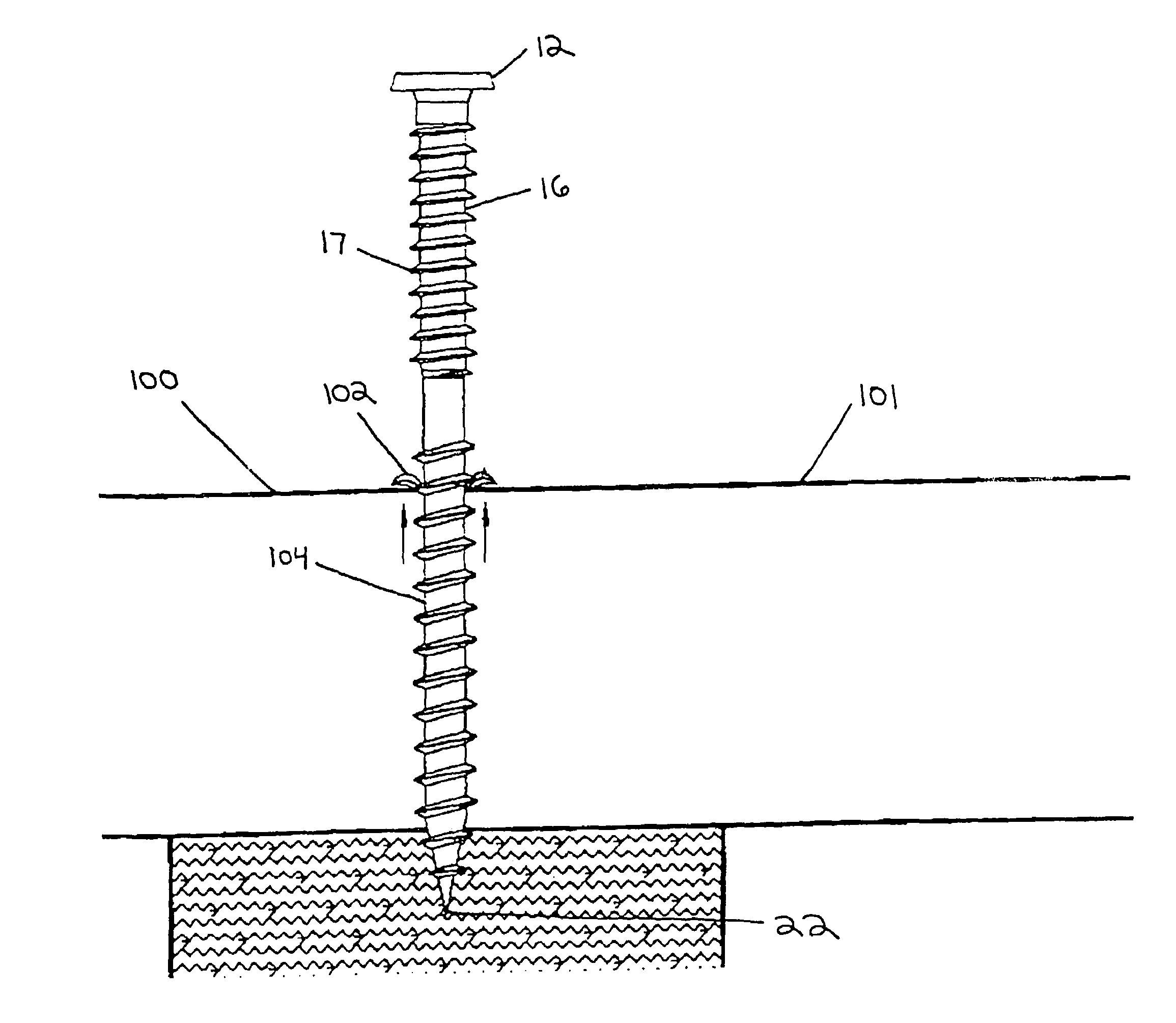
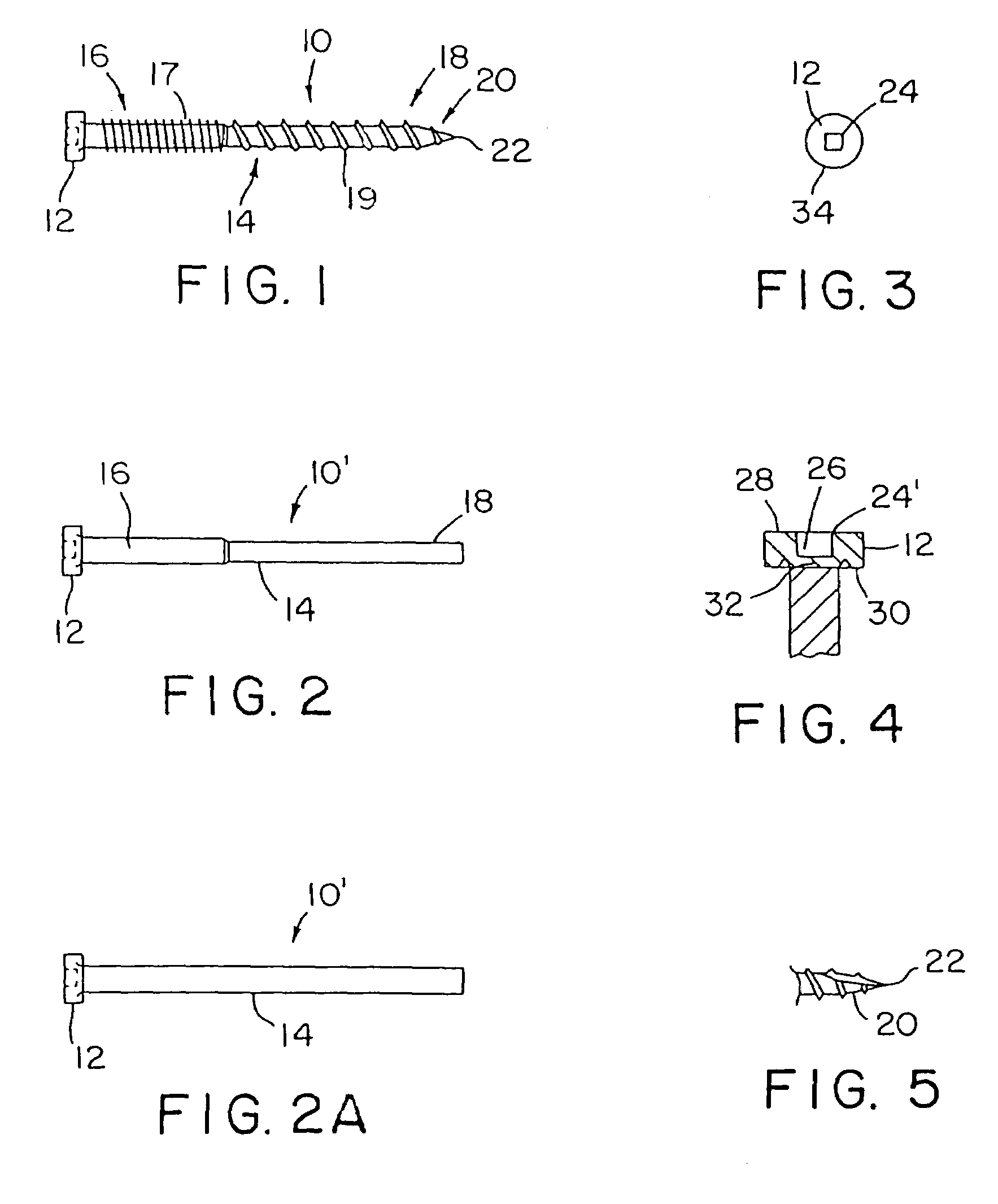
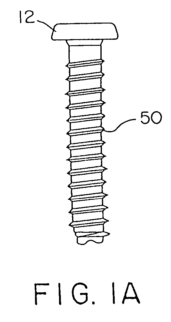
[0029]FIG. 1 shows a deck screw 10 of the present invention. As seen in the Figure, the deck screw is provided with a head 12 and shaft 14. FIG. 2 shows screw blank 10′, from which the deck screw 10 can be manufactured. The shaft 14 is provided with an upper region 16 that is closest to the head 12, and a lower region 18, closest to the tapered distal end 20 where the screw tip 22 is located. The cross sectional area of the upper region 16 is greater than the cross sectional area of the lower region, as seen in FIG. 2. FIG. 2A shows an embodiment where the cross sectional area of the upper and lower regions are substantially the same.

[0030]Tip 22 is provided with a sharp point to allow it to bore through the material. The tip may be a sharp gimlet tip such as one exhibiting a 20° to 30° included angle. The lower region 18 is provided with threads 19 such as one arrayed in a continuous helical thread that starts near or at the tip 22, proceeds over the tapered distal end 20, and over...


PUM

PropertyMeasurementUnit
flank angleaaaaaaaaaa

Abstract

A deck screw is intended for use with composite lumber, although it can be used with other wood products, such as pressure treated lumber. The deck screw has a head and a shaft that has two regions of different diameter. The upper region has threads that exceed the number of threads of the lower shaft, on a unit length basis. The threads of the upper shaft may be configured in an inverted buttress design. The lower region of the shaft terminates at a tapered distal end having a pointed tip that leads the screw through the wood material. Threads are provided on the lower region of the shaft. A crown extends around the perimeter of the head.

Description

RELATED APPLICATION[0001]This application is a continuation of U.S. patent application Ser. No. 09 / 923,288, filed on Aug. 6, 2001 now U.S. Pat. No. 6,966,737.FIELD OF THE INVENTION[0002]The present invention is directed to screws suitable for use in securing lumber, such as deck boards, in the construction of a deck. Notably, the screws are suitable for use with composite lumber.BACKGROUND OF THE INVENTION[0003]Having a deck associated with a residence or a commercial building, such as a bar or restaurant is highly desirable since it provides a place for outdoor gatherings. The presence of a deck enhances the value of the real estate of the residence or building. People have a natural preference for the outdoors when the weather is nice, whether one is having a backyard barbecue or relaxing with friends and neighbors. Restaurant patrons typically request outdoor seating on nice days and evenings, and often will wait for a table to become available, even though they could be seated i...

Claims


Application Information

Patent Timeline
Patent Type & Authority Patents(United States)
IPC IPC(8): F16B35/04F16B5/02F16B23/00F16B25/00F16B25/10F16B33/02F16B35/06
CPCF16B5/0275F16B25/0015F16B25/0031F16B25/0057F16B25/0063F16B25/10F16B35/041F16B35/065F16B25/0073F16B23/0007Y10T29/535F16B2033/025Y10T403/75
Inventor MCGOVERN, HUBERT T.DRUSCHEL, TOM
Owner OMG INC
Learn More