
Gas storage and delivery system for pressurized containers

a technology of gas storage and delivery system, which is applied in the field of pressurized containers, can solve the problems of reducing the pressure exerted by the propellant, limited use, and inability to disperse all the products from the container, and achieves better foaming, and consistent, uniform and acceptable spray patterns.

Inactive Publication Date: 2007-03-06
LIM WALTER K
View PDF19 Cites 28 Cited by
  • Summary
  • Abstract
  • Description
  • Claims
  • Application Information

AI Technical Summary

Benefits of technology

This solution ensures consistent pressure and product quality by releasing stored gas to maintain pressure, extending product life and reducing VOC content, thus addressing environmental concerns and cost issues.

Problems solved by technology

As product is depleted from the container, the pressure exerted by the propellant decreases, especially evident with compressed gases, and may become diminished to the extent that all of the product cannot be dispensed from the container, or desired characteristics are not achieved.
Volatile organic compounds (VOCs) such as propane, isobutane, dimethyl ether, and the like, are suitable as propellants for many products, but their use is limited due to environmental concerns.
Carbon dioxide (CO2) is environmentally friendly, and is therefore useful as an aerosol propellant, but its use has been limited due to the drop off in pressure from start to finish as the product is used.
At this low finishing pressure all of the product may not be discharged, and / or proper aerosolization may not be obtained.
The shelf life of such products may be undesirably short.
These materials are relatively expensive for the intended use.

Method used


Image

  • Gas storage and delivery system for pressurized containers
  • Gas storage and delivery system for pressurized containers
  • Gas storage and delivery system for pressurized containers

Examples


Embodiment Construction

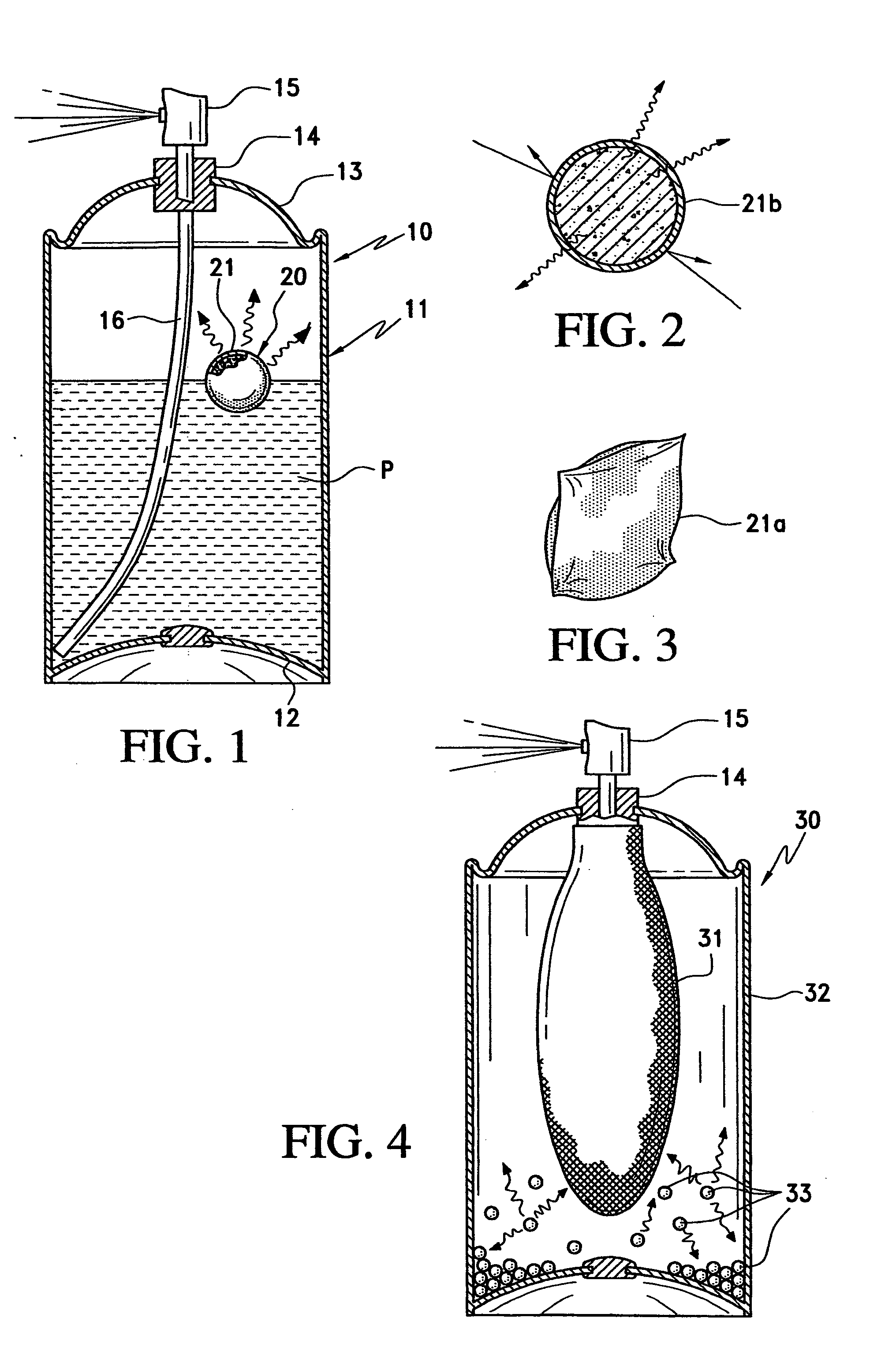
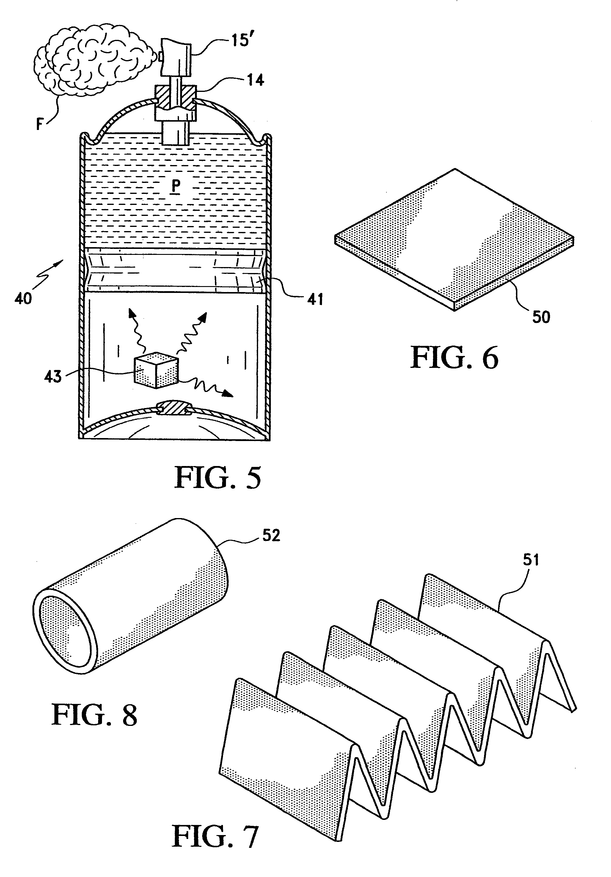
[0035]A first form of aerosol dispenser is indicated generally at 10 in FIG. 1. The dispenser includes a container 11 made of metal or other suitable material, having a bottom 12 and a top 13. A discharge nozzle assembly 14 is mounted on the top and includes a nozzle 15 that may be manually depressed to open and permit product P to be dispensed from the container through the nozzle. A dip tube 16 extends from the bottom of the container to the discharge nozzle assembly. As seen in this figure, the level of product in the container does not occupy the entire volume of the container, and the space above the product level is filled with a pressurized propellant gas to exert pressure on the product and force it through the dip tube and nozzle when the nozzle is depressed. The foregoing structure and operation are conventional.

[0036]In accordance with the invention, a storage body 20 of a gas-adsorbing material is placed in the container with the product to adsorb and store a quantity of...


PUM


Abstract

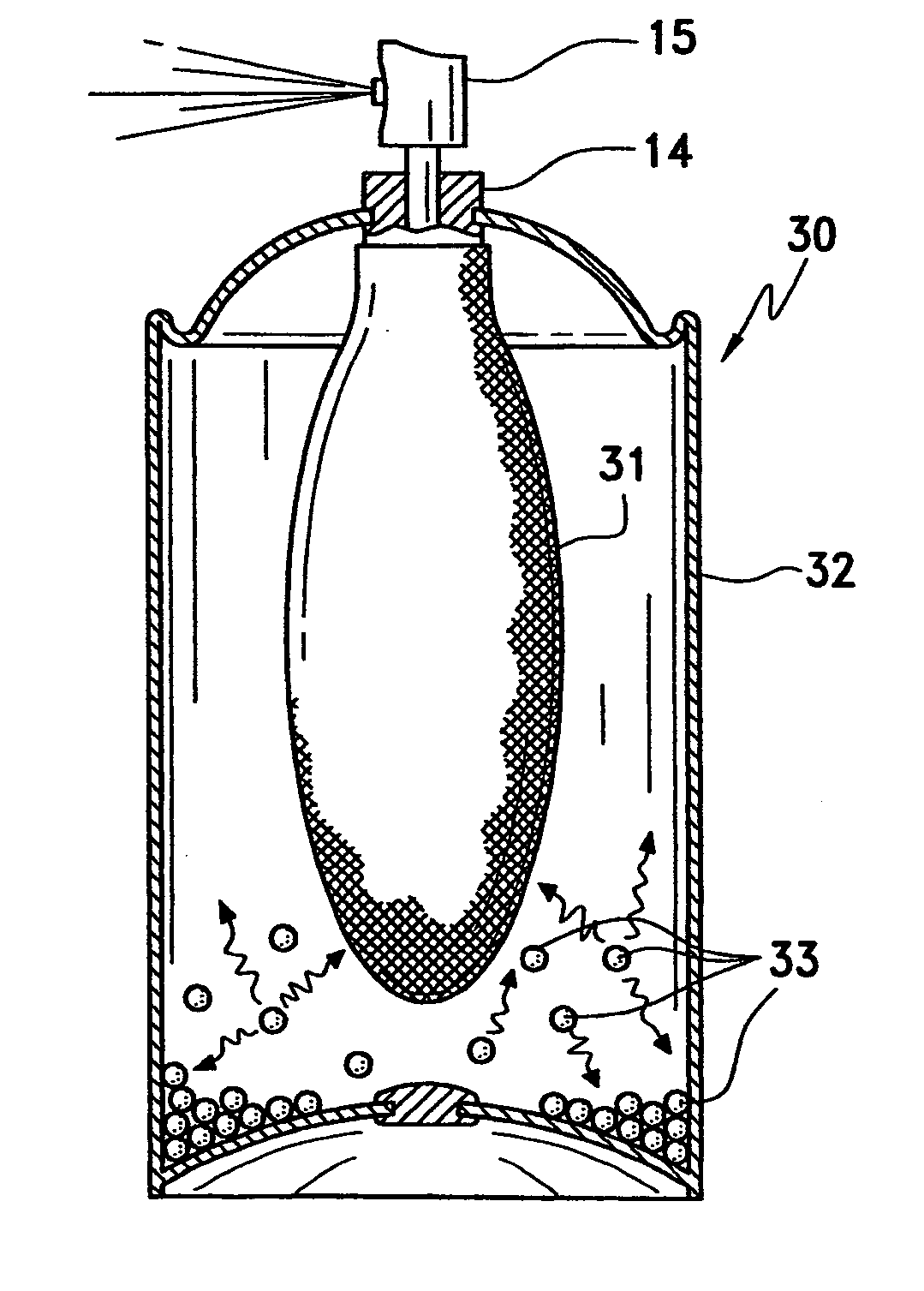
A gas adsorption material containing a desired quantity of gas is placed in a pressurized container along with a product to be dispensed, and as pressure in the container is depleted during use, stored gas is released into the container to maintain pressure in the container within a predetermined range. The material may be in contact with the product, or it may be isolated from the product, and is known as a pressure swing adsorption (PSA) system, wherein adsorption of gas into the material occurs at a high pressure, and desorption of gas from the material occurs at a low pressure. Such devices are capable of storing under pressure a volume of gas 18 to 20 times the volume of the material. A preferred adsorbent gas storage material is granular activated carbon, or a carbon fiber composite molecular sieve (CFCMS). Other materials, such as zeolite, starch-based polymers, activated alumina, silica gel, and sodium bicarbonate, or mixtures thereof, may be used, although they generally are not as effective as activated carbon. The adsorbent material may be in granular, powdered, or pellet form, or a mass of the material may be formed into variously shaped cohesive bodies, such as balls, tubes, cubes or rods, or sheets or screens which may be flat or curved or folded into various shapes, such as, for example, an accordion-like fold.

Description

BACKGROUND OF THE INVENTION[0001]1. Field of the Invention[0002]This invention relates generally to pressurized containers, and more particularly, to a gas storage and delivery system for restoring and maintaining pressure as it is depleted from pressurized containers such as aerosol dispensers, bottles of carbonated beverage, fire extinguishers using water or foam, and the like.[0003]2. Prior Art[0004]Pressurized containers are commonly used to dispense many products, including paint, lubricants, cleaning products, hair spray, and food items. These containers are typically aerosol dispensers in which the product is stored under pressure with a suitable propellant. Dispensing of the product occurs when a discharge nozzle is depressed, permitting the pressurized product to be forced out through the nozzle, usually as a spray, stream or foam. As product is depleted from the container, the pressure exerted by the propellant decreases, especially evident with compressed gases, and may b...

Claims


Application Information

Patent Timeline
Patent Type & Authority Patents(United States)
IPC IPC(8): B65D83/62B65D83/64B65D83/14B67B7/00
CPCB65D83/62B65D83/663B65D83/64Y02W90/10
Inventor KRAUSE, ARTHUR A.LIM, WALTER K.
Owner LIM WALTER K
Learn More