High frequency receiving device, integrated circuit used for the same, and TV receiver using them

a technology of high frequency and receiving device, which is applied in the direction of television system, multi-resonant circuit tuned to different frequencies, and discontnuous tuning with seperate pre-tuned circuits, etc., can solve the problem that certain frequency ranges cannot be received, and achieve the effect of widening the oscillation frequency rang

Inactive Publication Date: 2007-02-27
PANASONIC CORP
View PDF19 Cites 11 Cited by
  • Summary
  • Abstract
  • Description
  • Claims
  • Application Information

AI Technical Summary

Benefits of technology

[0024]And, the oscillation frequency changing means, in each receiving frequency band, slightly changes the oscillation frequency characteristic of the local oscillator in relation to the tuning voltage supplied from the PLL circuit, and when receiving the first frequency band, it operates in accordance with the frequency characteristic of the first tuning filter, and also, when receiving the second frequency band, it operates in accordance with the frequency characteristic of the second tuning filter, thereby obtaining a local oscillation signal varied just by a predetermined frequency.
[0026]Thus, for example, when receiving the second frequency band, the oscillation frequency characteristic of the local oscillator is slightly changed by the oscillation frequency changing means, and thereby, it becomes possible to attain such operation as to obtain a local oscillation signal of a frequency range corresponding to the second frequency band such as widening the oscillation frequency range. Further, the frequency divider and the oscillation frequency changing means are properly changed over, and thereby, it is also possible to produce a local oscillation signal of a frequency that is continuous in a range from VHF to UHF, and all channels can be received even when they are continuous between the first receiving band and the second receiving band. Accordingly, in TV broadcast, it is possible to realize a high frequency receiving device capable of receiving broad-band channels of continuous VHF broadcast band and UHF broadcast band.

Problems solved by technology

However, in such a conventional high frequency receiving device, there arises a subject such that within the tuning voltage variable range there is a frequency range that cannot be oscillated, and a certain frequency range cannot be received.

Method used


Image

  • High frequency receiving device, integrated circuit used for the same, and TV receiver using them
  • High frequency receiving device, integrated circuit used for the same, and TV receiver using them
  • High frequency receiving device, integrated circuit used for the same, and TV receiver using them

Examples


first preferred embodiment

(First Preferred Embodiment)

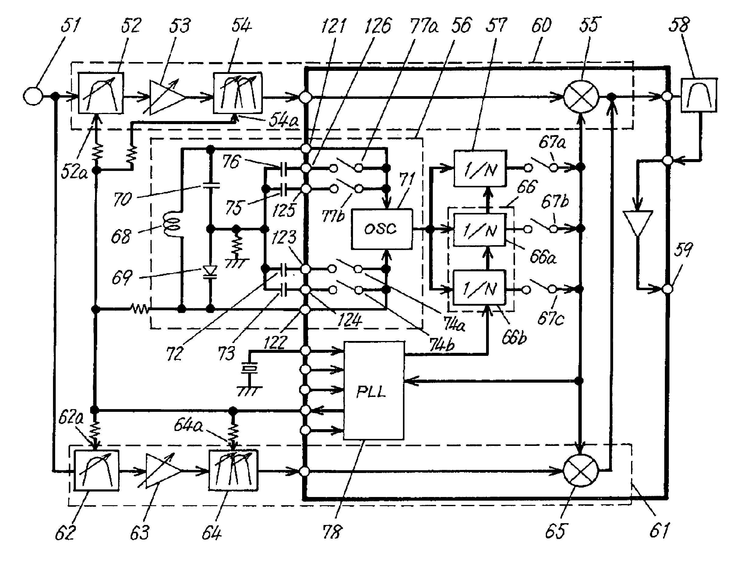
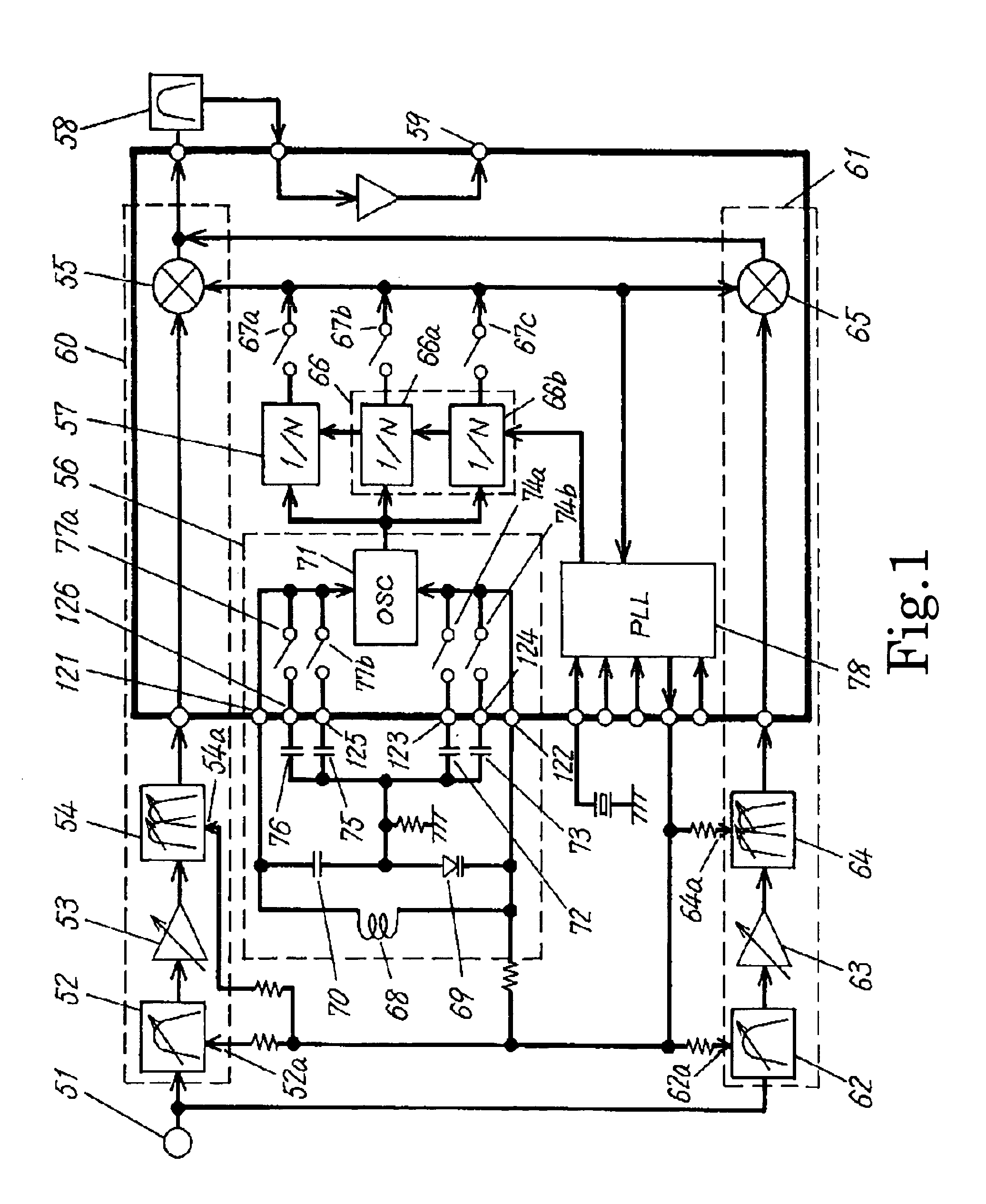
[0036]The first preferred embodiment of the present invention will be described in the following with reference to the drawings. FIG. 1 is a block diagram of a high frequency receiving device in the first preferred embodiment.

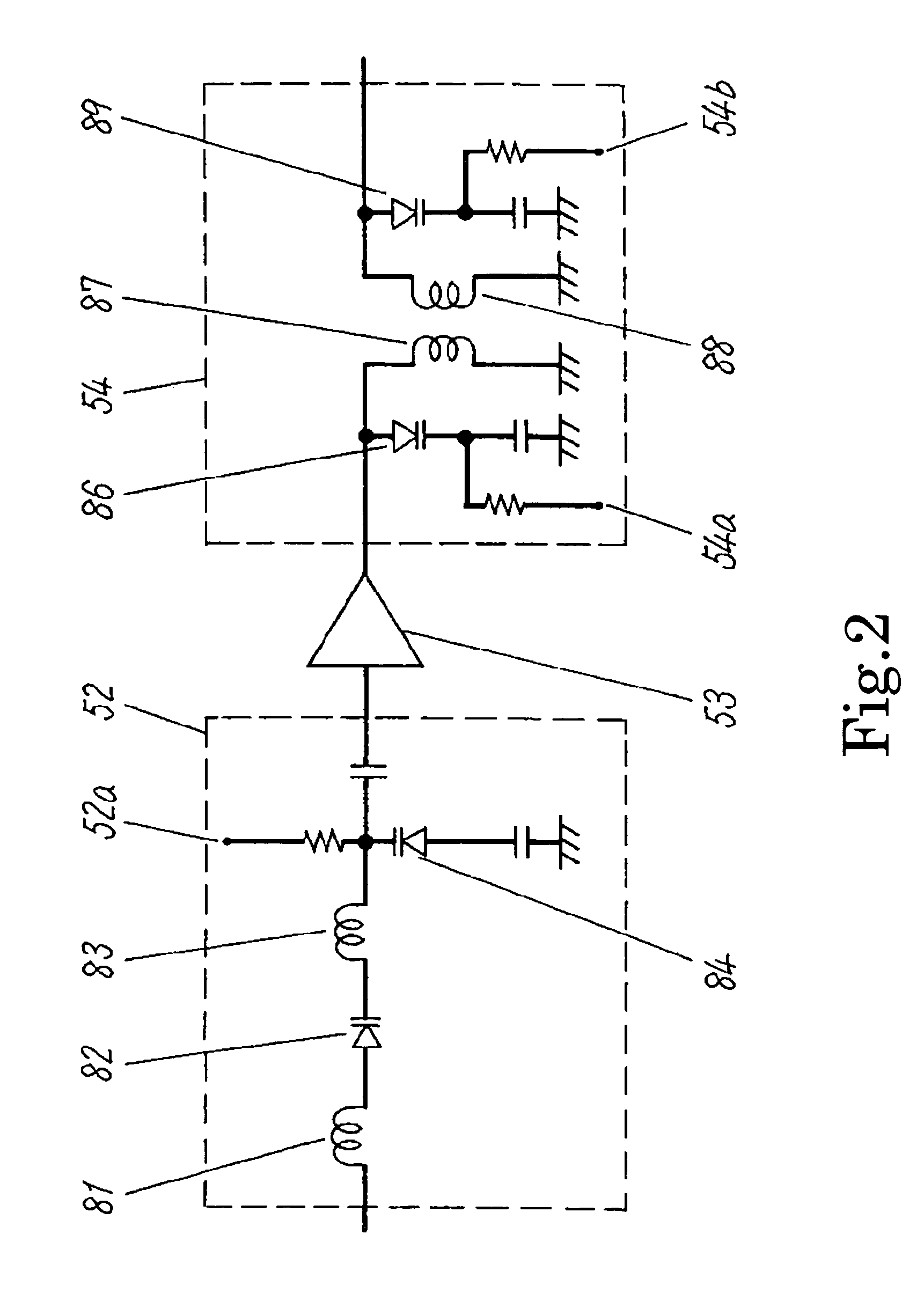
[0037]In FIG. 1, a high frequency signal ranging from 55.25 MHz to 801.25 MHz is inputted to input terminal 51. The high frequency signal is fed to single tuning filter 52. The single tuning filter 52 is a single tuning filter including one variable capacity diode, and is able to vary the tuning frequency by using the tuning voltage applied to frequency variable terminal 52a. The tuning frequency of single tuning filter 52 ranges from 367.25 MHz to 801.25 MHz of UHF broadcast band.

[0038]The output of single tuning filter 52 is connected to high frequency amplifier 53, and high frequency amplifier 53 amplifies the signal of UHF broadcast band. The output of high frequency amplifier 53 is connected to double tuning filter 54. The doubl...

second preferred embodiment

(Second Preferred Embodiment)

[0093]In the second preferred embodiment, UHF broadcast band and VHF broadcast band are received by using only one mixer. Accordingly, it contributes to the reduction in size and cost. The second preferred embodiment will be described in the following. Incidentally, those same as in the first preferred embodiment are given same reference numerals, and the description is simplified.

[0094]FIG. 5 is a block diagram of a high frequency receiving device in the second preferred embodiment. In FIG. 5, broadcasting waves of UHF broadcast band and VHF broadcast band are inputted to input terminal 132. And, to input terminal 132 are connected in parallel fashion, for UHF broadcast band passing, the first series connection body with single tuning filter 52, high frequency amplifier 53, and double tuning filter 54 connected in this order, and for VHF broadcast band passing, the second series connection body with single tuning filter 62, high frequency amplifier 63, ...

third preferred embodiment

(Third Preferred Embodiment)

[0100]The third preferred embodiment will be described in the following with reference to the drawings. FIG. 6 is a block diagram of an essential portion of a television broadcast receiver using a high frequency receiving device in the third preferred embodiment. In the third preferred embodiment, same component elements as those in the first preferred embodiment are given same reference numerals, and the description is simplified.

[0101]In FIG. 6, single tuning filter 52 is connected to input terminal 51, and includes one variable capacity diode. Single tuning filter 52 is able to vary its tuning frequency by using the tuning voltage applied to frequency variable terminal 52a in a range from 367.25 MHz to 801.25 MHz of UHF broadcast band.

[0102]Double tuning filter 54 is connected to the output of high frequency amplifier 53. Double tuning filter 54 includes two variable capacity diodes and is able to vary its tuning frequency by using the tuning voltage a...


PUM


Abstract

An oscillation frequency changing means is inserted between a tuner and an oscillator of local oscillator (56) of a high frequency receiving device, and the oscillation frequency changing means, in each frequency band received, changes the oscillation frequency characteristic of local oscillator (56) in relation to the tuning voltage supplied from PLL circuit (78), and operates in accordance with the frequency characteristic of tuning filter (52, 54, 62, 64) to obtain an oscillation signal varied just by a predetermined frequency, thereby making it possible to receive broadband channels of continuous VHF broadcast band and UHF broadcast band.

Description

BACKGROUND OF THE INVENTION[0001]1. Field of the Invention[0002]The present invention relates to a high frequency receiving device used for a TV receiving tuner or the like, and an integrated circuit used for the same.[0003]2. Description of the Related Art[0004]A conventional high frequency receiving device will be described in the following with reference to the drawings. FIG. 8 is a block diagram of a conventional high frequency receiving device.[0005]In FIG. 8, a high frequency signal ranging from 55.25 MHz to 801.25 MHz is inputted to input terminal 1. The high frequency signal is fed to single tuning filter 2 that is a single tuning type filter. The single tuning filter 2 includes one variable capacity diode and is able to vary the tuning frequency by using a tuning voltage applied to frequency variable terminal 2a. The tuning frequency of single tuning filter 2 is within the range of UHF broadcast band (367.25 MHz to 801.25 MHz).[0006]The output of single tuning filter 2 is c...

Claims


Application Information

Patent Timeline
Patent Type & Authority Patents(United States)
IPC IPC(8): H04B1/06H03J3/20H03J3/28H03J5/00H03J5/24H04B1/16H04B1/18H04B1/40H04B7/00H04N5/44
CPCH03J3/28H03J5/244H03J2200/36
Inventor ASAYAMA, SANAENAKATSUJI, KOJITERAO, ATSUHITOTABATA, YOSHIHIDETAKAMI, HIDEJISUZUKI, MASANORIKASHIMA, HIROCHIKA
Owner PANASONIC CORP
Why Eureka
Try Eureka