Stacked microphone jack assembly

a microphone jack and stacked technology, applied in the direction of coupling devices, two-part coupling devices, electrical apparatus, etc., can solve the problems of increasing the manufacturing cost of these metal contact terminals, increasing the manufacturing cost, and complicating inventory control, so as to examine the fabricated microphone jack quickly and efficiently

Active Publication Date: 2007-02-27
LIH SHENG PRECISION INDAL
View PDF5 Cites 1 Cited by
  • Summary
  • Abstract
  • Description
  • Claims
  • Application Information

AI Technical Summary

Benefits of technology

[0014]The present invention has been accomplished under the circumstances in view. According to one aspect of the present invention, two identical microphone jacks can be assembled with a connector to form a stacked microphone jack assembly for the insertion of two microphones. Because the microphone jacks are identical, the parts of the microphone jacks can be modularized for easy fabrication in an economic way.
[0015]According to another aspect of the invention, one single design of microphone jacks can be used with one connector to construct a stacked microphone jack assembly. Therefore, the invention facilitates the inventory control of microphone jacks. Further, every individual microphone jack according to the present invention can be independently used.
[0016]According to still another aspect of the present invention, the legs of the conducting terminals of the microphone jacks are designed to be relatively shorter than the legs of the connection terminals of the connector. Further, the conducting terminals of the microphone jacks are made of an expensive metal material having the advantages of high structural strength, high resilience work of deformation and long service life, and the connection terminals of the connector are made of a relatively cheaper metal material. This design greatly reduces the terminal material cost without affecting the performance of the stacked microphone jack assembly.
[0018]According to still another aspect of the present invention, the connector of the present invention can be used one microphone jack and stacked on the microphone jack at the top and then positioned with the underlying microphone jack in respective contacts of the test instrument, and microphone jacks can then be stacked on the connector and tested one after another. Thus, a big amount of microphone jacks can quickly be examined. Therefore, the invention can examine fabricated microphone jacks rapidly and efficiently.
[0019]According to still another aspect of the present invention, he connector of the stacked microphone jack assembly keeps the front plugholes of the housings of the two microphone jacks spaced at a sufficient distance so that the plugs of two microphones can be respectively inserted into the front plugholes of the two microphone jacks without interference.

Problems solved by technology

Therefore, the manufacturing cost of these metal contact terminals B1 and B2 is high.
If a cheap metal material is used for making these metal contact terminals B1 and B2, the electrical socket B will wear quickly with use.
2. Because the metal contact terminals B1 and B2 of the overlying electrical socket B and the metal contact terminals A1 and A2 of the underlying electrical socket A have different shapes, two different stamping molds should be used, thereby increasing the manufacturing cost and complicating the inventory control.
3. Because the overlying electrical socket B and the underlying electrical socket A have different specifications, the inventory cost is greatly increased.
Therefore, this design is not an economic design.
When one electrical socket failed, the whole stacked electrical socket assembly becomes useless and must be wholly replaced.
This test procedure is complicated, wasting much time and labor.

Method used


Image

  • Stacked microphone jack assembly
  • Stacked microphone jack assembly
  • Stacked microphone jack assembly

Examples


Embodiment Construction

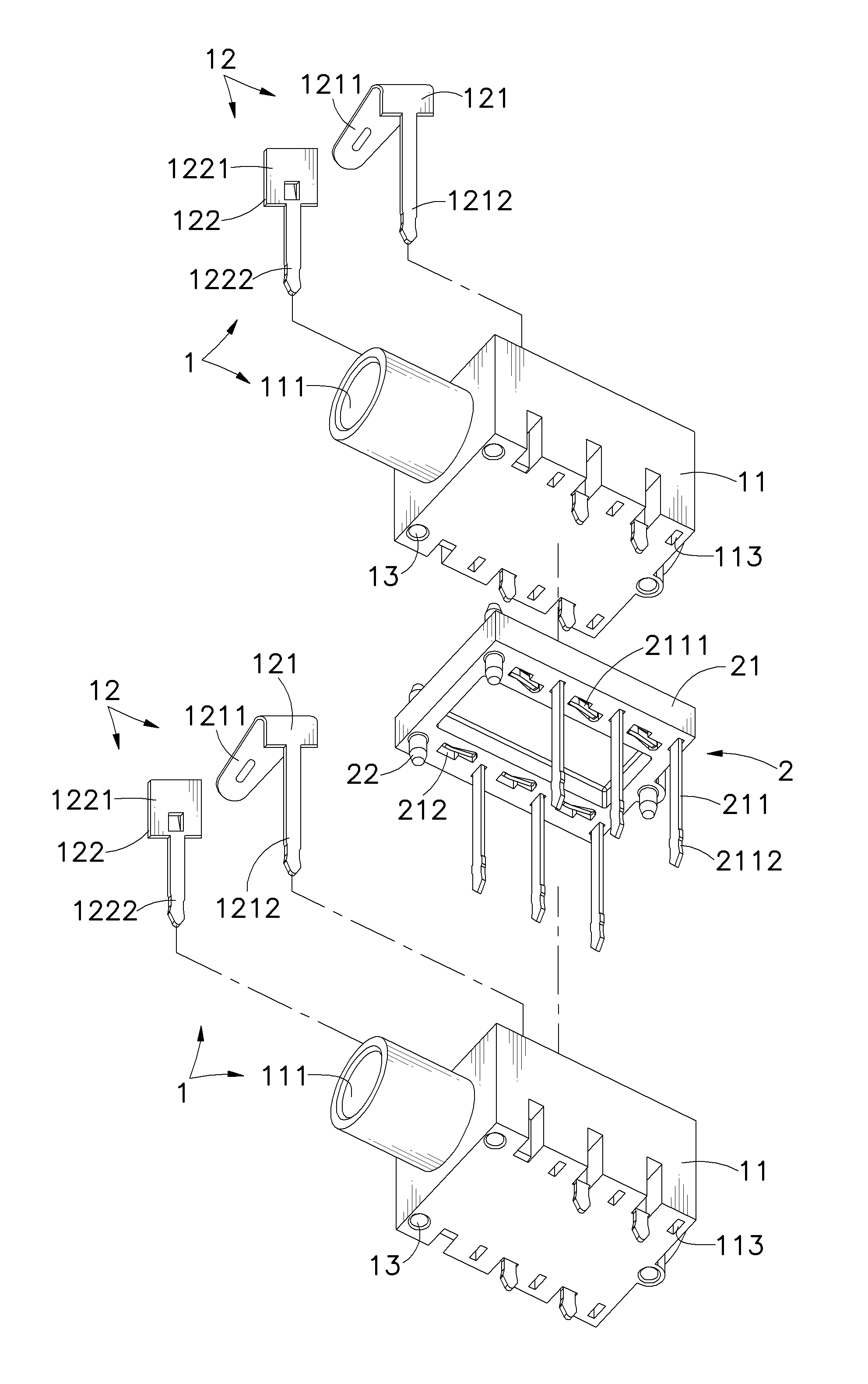
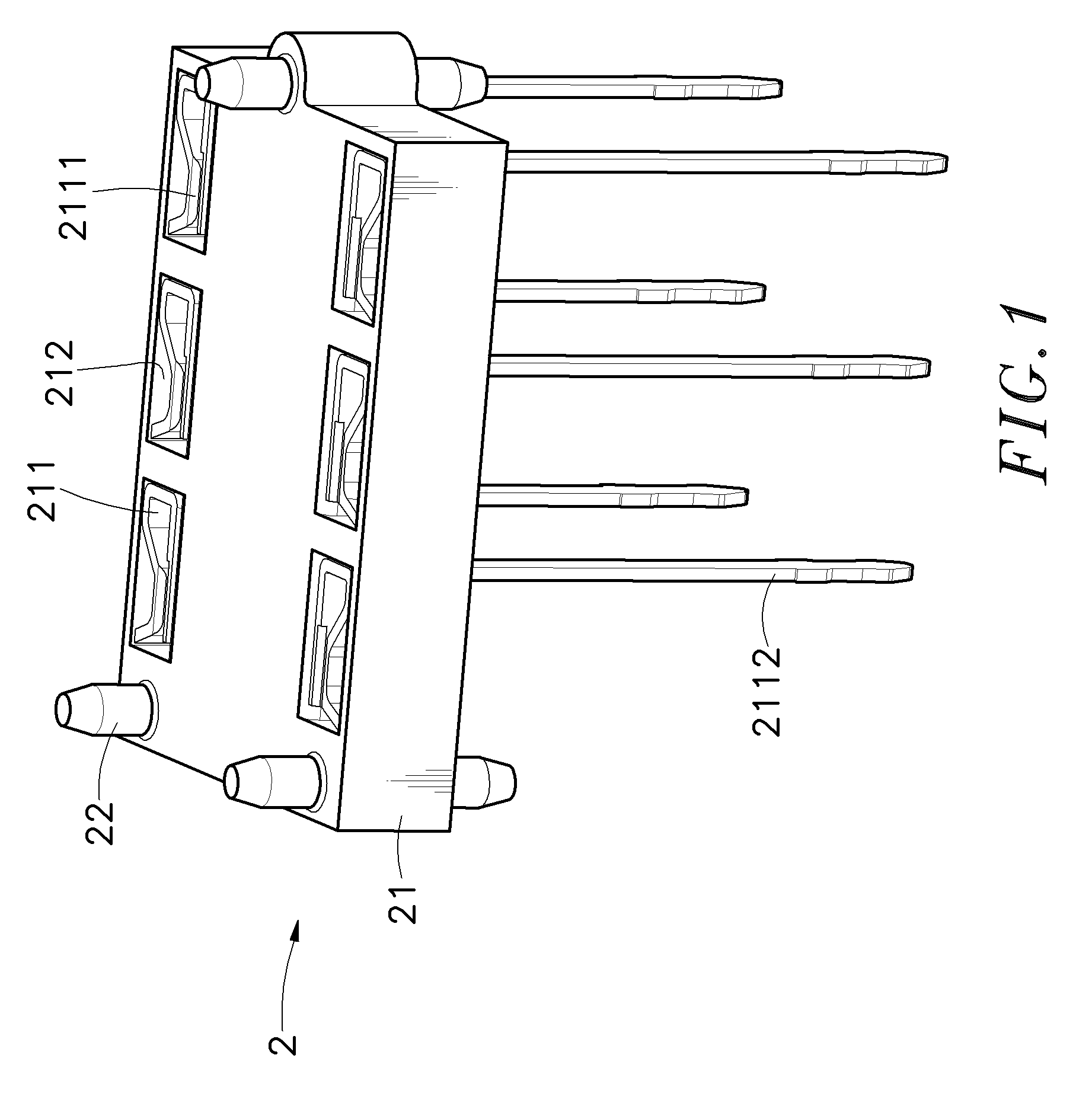
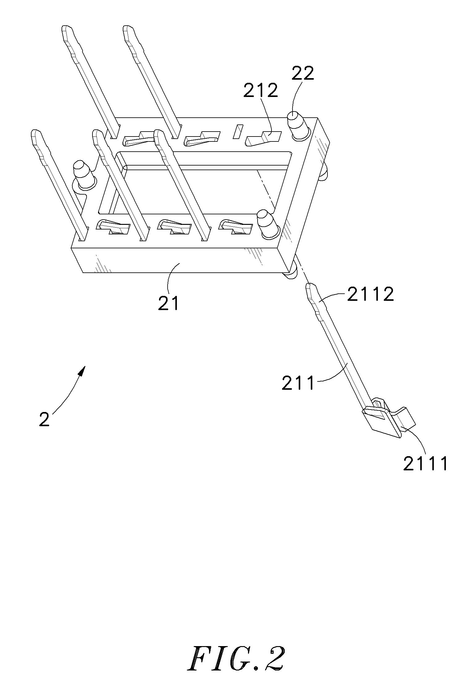
[0031]Referring to FIGS. 1˜6, a stacked microphone jack assembly in accordance with the present invention is generally comprised of two microphone jacks 1, and a connector 2 electrically connected between the two microphone jacks 1.

[0032]The microphone jacks 1 are identical, each comprised of an electrically insulative housing 11 and a set of conducting terminals 12. The housing 11 has an inside chamber 112, a front plughole 111 disposed in communication with the inside chamber 112 at a front side for receiving a microphone plug, and a plurality of vertical through holes 113 vertically cut through the top and bottom walls thereof near two opposite lateral sides. The conducting terminals 12 include contact terminals 121 and detection terminals 122 respectively mounted in the housing 11 at two opposite lateral sides. The contact terminals 121 each have a head 1211 and a leg 1212 downwardly extending from one side of the head 1211. The detection terminals 122 each have a head 1221 and ...


PUM


Abstract

A stacked microphone jack assembly includes two identical microphone jacks each having a housing, which has a front plughole for receiving a microphone plug and two rows of vertical through holes, and conducting terminals each having a head extending to the inside of the housing for the contact of the plug of a microphone and a leg downwardly extending out of the bottom side of the housing, and a connector, which has a base sandwiched between the housings of the two microphone jacks, and a connection terminals respectively fastened to terminal slots on the base, each connection terminal having a clamping portion for clamping the legs of the conducting terminals of the overlying microphone jack respectively and a leg downwardly extending from the clamping portion and respectively inserted through the vertical through holes of the underlying microphone jack.

Description

[0001]This application is a Continuation-In-Part of my patent application Ser. No. 11 / 160,206, filed on Jun. 14, 2005.BACKGROUND OF THE INVENTION[0002]1. Field of the Invention[0003]The present invention relates to microphone jacks and more particularly, to a stacked microphone jack assembly, which uses a connector to connect two identical microphone jacks to form a stacked microphone jack assembly. The microphone jacks can be individually used when detached.[0004]2. Description of the Related Art[0005]Following fast development of high technology, advanced electronic and electric products have been continuously created to improve people's living standard and to promote higher living quality. Among various electronic and electric products, TV, stereo system, CD / DVD / VCD / VDV player are frequently used at home to help people release stress. Further, many electronic and electric products have audio and video plugs for output of audio and video signals to other electronic and / or electric...

Claims


Application Information

Patent Timeline
Patent Type & Authority Patents(United States)
IPC IPC(8): H01R13/60
CPCH01R12/716H01R24/58H01R13/514H01R2107/00
Inventor HUANG, CHEN-CHIH
Owner LIH SHENG PRECISION INDAL
Why Eureka
Try Eureka