
Technique for controlling selection of a peek adapter or a read adapter from multiple adapters connected to a high speed switch

a high-speed switch and adapter technology, applied in the field of distributed computer systems, can solve the problems of slow data reading, increased path length, slow application, etc., and achieve the effect of enhancing performance and minimizing switching overhead

Inactive Publication Date: 2007-02-13
INT BUSINESS MASCH CORP
View PDF26 Cites 12 Cited by
  • Summary
  • Abstract
  • Description
  • Claims
  • Application Information

AI Technical Summary

Benefits of technology

The patent text describes a method for optimizing the reading of data from multiple adapters in a distributed computing environment. The method uses filters to select the best adapter for reading each message, based on factors like the speed of the adapter and the path length between the message and the adapter. This technique helps applications that need to read more data than one adapter can provide to use multiple adapters without slowing down the overall system. The method also allows applications to switch between adapters quickly and efficiently, improving performance and minimizing overhead. Overall, the technique presented in the patent text helps applications to use multiple adapters while still performing at the same or greater speed as using a single adapter.

Problems solved by technology

Although multiple adapters are assumed to facilitate the reading of data faster than a single adapter, it has been discovered by applicants that this is not always the case.
If the speed at which the data can be read is limited by the path length of the computer program, multiple adapters can actually slow down the reading of data, i.e., the increased path length for switching between adapters slows down the application.
This can create a situation where applications actually run slower on multiple adapters than on one adapter.
In one embodiment, the second filter is more complicated and time consuming than the first filter.

Method used


Image

  • Technique for controlling selection of a peek adapter or a read adapter from multiple adapters connected to a high speed switch
  • Technique for controlling selection of a peek adapter or a read adapter from multiple adapters connected to a high speed switch
  • Technique for controlling selection of a peek adapter or a read adapter from multiple adapters connected to a high speed switch

Examples


Embodiment Construction

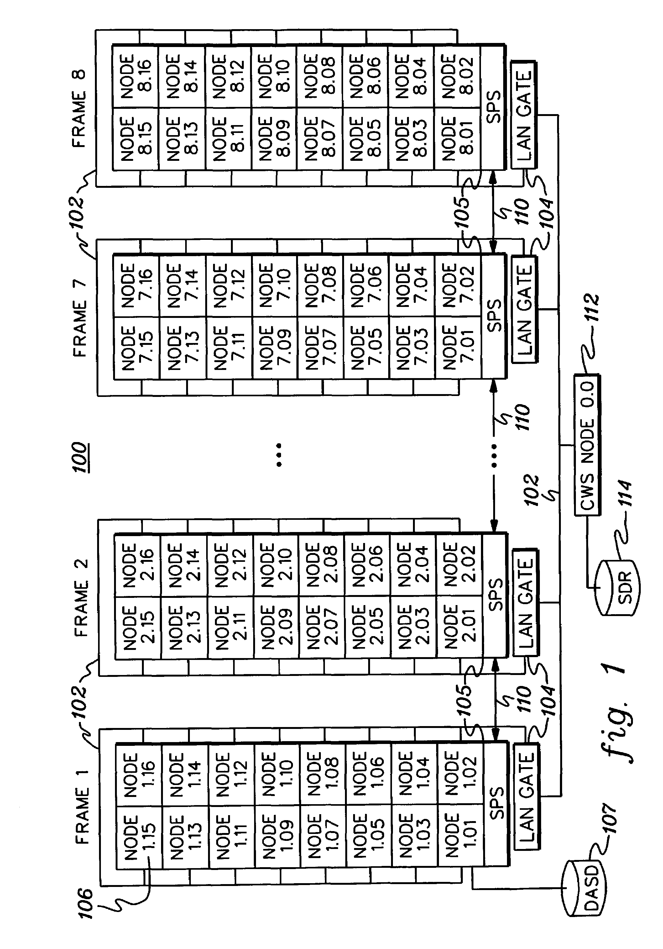
[0023]FIG. 1 is a schematic diagram of a distributed computer system 100 incorporating and using aspects of the present invention. As one example, the distributed computer system 100 may be an IBM RISC System / 6000 Scalable POWERparallel Systems (SP) distributed computer system available from International Business Machines Corporation of Armonk, N.Y. The embodiment disclosed in FIG. 1 is an SP computing environment having a total of 8 frames, with each frame having up to 16 processing nodes, for a total of 128 nodes. All of the nodes 106 are joined by a local area network (LAN) 102. Each processing node 106 is a computer itself, and may (for instance) be a RISC System / 6000 computer running AIX, a UNIX based operating system well-known by those skilled in the art.

[0024]All of the nodes in a frame of the SP computer 100 are included in a LAN segment which is joined by the other LAN segments through LAN gates 104. As examples, each LAN gate 104 includes either a RISC / 6000 computer, any...


PUM


Abstract

A technique is provided for facilitating peeking and reading of messages from multiple adapters connected, for example, to a high speed switch in a distributed computing environment. The technique employs a first, relatively quick filter to initially test whether a previously used adapter of the multiple adapters should be used to peek or read a new message. If the first filter fails to select the previously used adapter, then the technique includes employing a second, more complicated filter to determine which adapter of the multiple adapters should be used to peek or read the next message. The first filter includes a first set of tests, and the second filter includes a second set of tests.

Description

CROSS-REFERENCE TO RELATED APPLICATION[0001]This application contains subject matter which is related to the subject matter of the following application, which is assigned to the same assignee as this application and filed on the same day as this application. The below-listed application is hereby incorporated herein by reference in its entirety:[0002]“TECHNIQUE FOR CONTROLLING SELECTION OF A WRITE ADAPTER FROM MULTIPLE ADAPTERS CONNECTED TO A HIGH SPEED SWITCH”, by William S. Cadden, Ser. No. 11 / 457,612.TECHNICAL FIELD[0003]This invention relates in general to a distributed computer system having a plurality of data processing nodes and one or more switch units which establish links between the plurality of processing nodes, and more particularly, to a technique for controlling selection of an adapter, from multiple adapters, for viewing or reading a message in an associated buffer in order to enhance overall message processing performance.BACKGROUND OF THE INVENTION[0004]In certai...

Claims


Application Information

Patent Timeline
Patent Type & Authority Patents(United States)
IPC IPC(8): H04J3/16G06F15/16H04L12/56
CPCH04L49/1523H04L49/30H04L49/552
Inventor CADDEN, WILLIAM S.
Owner INT BUSINESS MASCH CORP
Learn More