
Year-round decorative lights with multiple strings of series-coupled bipolar bicolor LEDs for selectable holiday color schemes

a technology of series-coupled bipolar bicolor leds and decorative lights, which is applied in the field of decorative lights, can solve the problems of limited use of particular colors, unattractive non-lit bulbs along the light strand, and difficulty in finding the light strand for these occasions, so as to reduce the number of non-lit lamps and eliminate the effect of wired lines

Inactive Publication Date: 2007-02-13
YEAR ROUND CREATIONS
View PDF46 Cites 70 Cited by
  • Summary
  • Abstract
  • Description
  • Claims
  • Application Information

AI Technical Summary

Benefits of technology

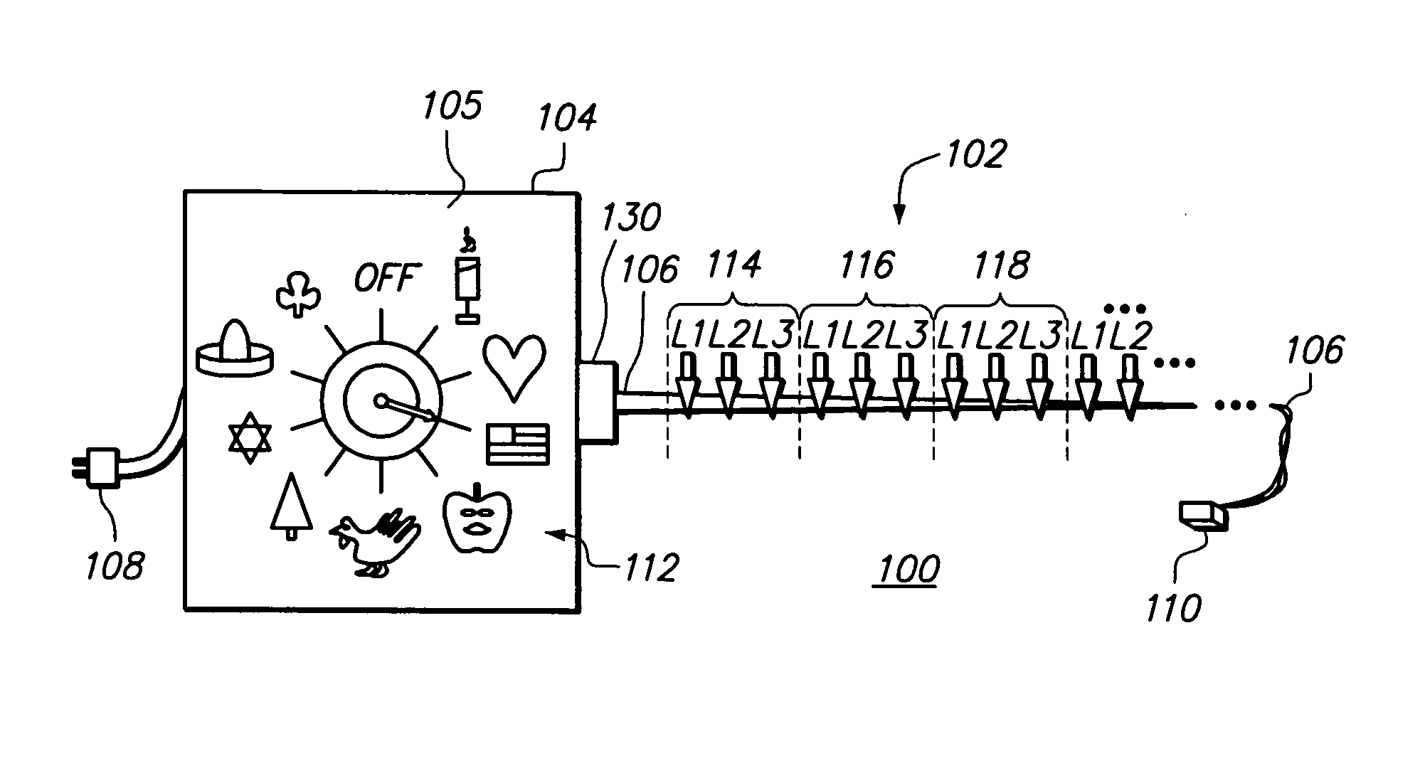
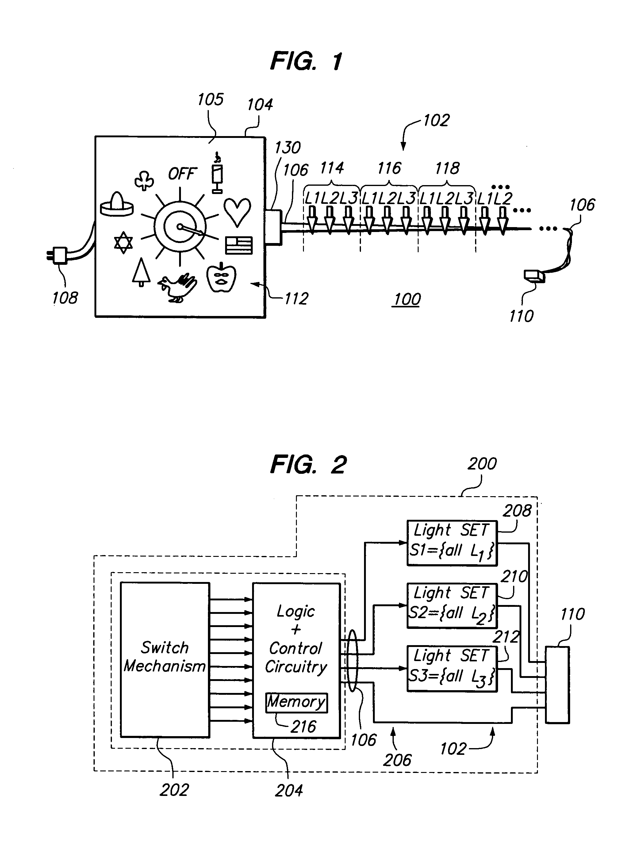
"The present invention is a decorative lighting apparatus that provides user-selectable color schemes for several holidays and other occasions. The apparatus includes a decorative light strand with multiple wires and lamps, each containing an LED device. The lamps are positioned together to prevent color mixing, and a controller is used to control the illumination of each lamp. The apparatus can be hung permanently and used for major holidays and other suitable themes. The use of LEDs provides flexibility in color choice, reduces the number of non-lit lamps, and increases the lifespan of the light strand. The apparatus also reduces the number of wired lines to the lamps."

Problems solved by technology

Holidays other than Christmas are celebrated as well, although light strands for these occasions are difficult to find if they even exist at all.
In addition, there may be unattractive non-lit bulbs along the light strand in at least some selected color schemes.
Finally, although such a light strand provides for different color schemes, there may be limitations on which particular colors are utilized (e.g. uncommon colors such as purple or pink may not be provided).

Method used


Image

  • Year-round decorative lights with multiple strings of series-coupled bipolar bicolor LEDs for selectable holiday color schemes
  • Year-round decorative lights with multiple strings of series-coupled bipolar bicolor LEDs for selectable holiday color schemes
  • Year-round decorative lights with multiple strings of series-coupled bipolar bicolor LEDs for selectable holiday color schemes

Examples


Embodiment Construction

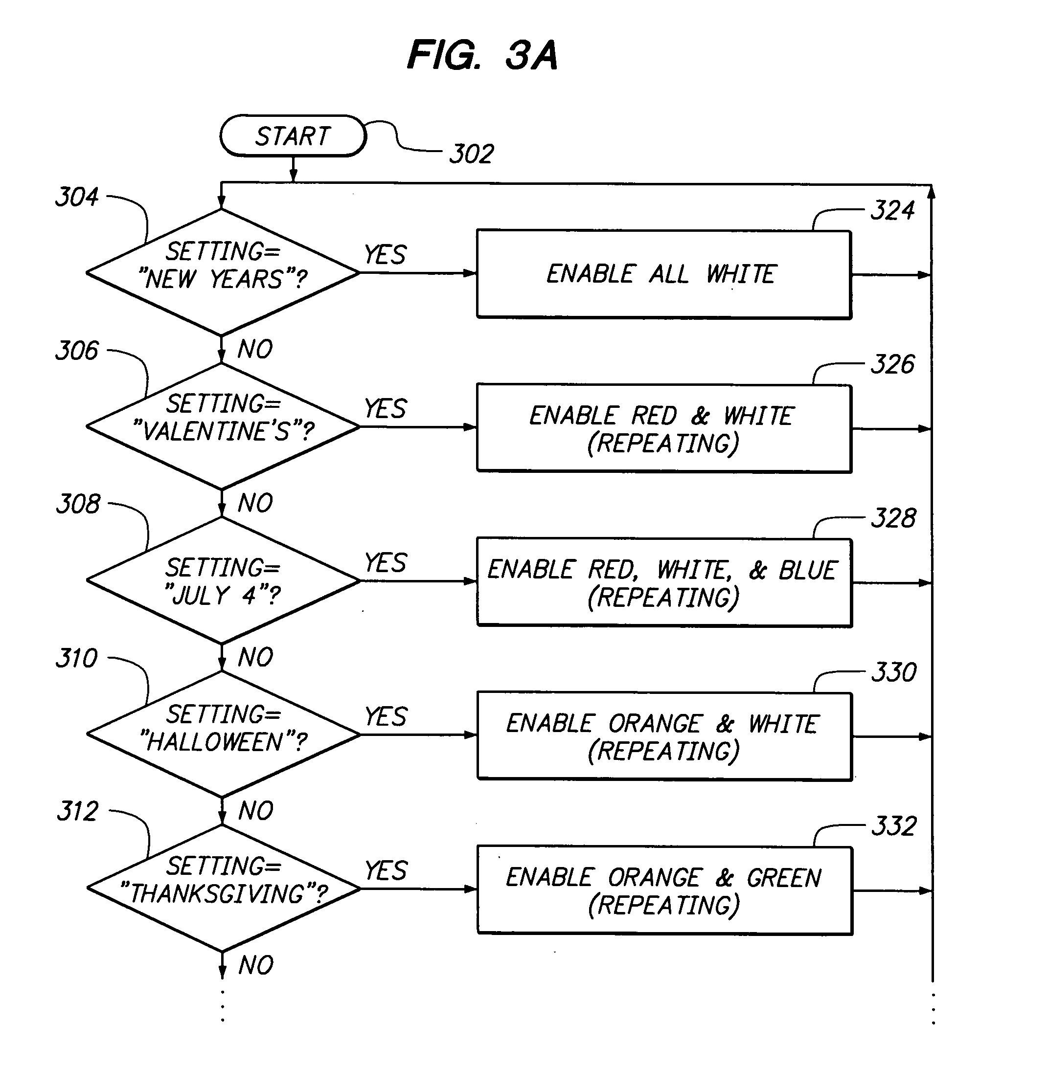
[0027]A decorative lighting apparatus provides user-selectable color schemes corresponding to several holidays, and other occasions and themes, for year-round use. In one illustrative example, a decorative lighting apparatus includes a decorative light strand having a first wire with a first plurality of lamps coupled in series therealong, a second wire with a second plurality of lamps coupled in series therealong, a third wire with a third plurality of lamps coupled in series therealong, and a return wire coupled to ends of the first, the second, and the third wires. Each lamp of the first plurality has a first light-emitting diode (LED) device (e.g. red) which is coupled in parallel and in reverse orientation with a second LED device (e.g. orange / yellow), each lamp of the second plurality has a third LED device (e.g. blue) which is coupled in parallel and in reverse orientation with a fourth LED device (e.g. green), and each lamp of the third plurality has at least a fifth light-e...


PUM


Abstract

A decorative lighting apparatus includes a decorative light strand having first, second, and third wires, each with a plurality of lamps coupled in series therealong, and a return wire coupled to ends of the first, the second, and the third wires. Each lamp of the plurality of lamps has a first light-emitting diode (LED) device coupled in parallel and in reverse orientation with a second LED device. The first, the second, and the third wires are positioned together such that each lamp of the first, the second, and the third pluralities are positioned adjacent to each other but sufficiently separated such that little or no color mixing occurs between the lamps. The apparatus also includes a controller adapted to control the plurality of lamps to provide different user-selectable color schemes in various simultaneously-illuminated combinations of color.

Description

CROSS-REFERENCE TO RELATED APPLICATIONS[0001]This application is a continuation-in-part of U.S. patent application Ser. No. 10 / 678,934 filed on Oct. 3rd, 2003 now U.S. Pat. No. 6,933,680 entitled “Decorative Lights With At Least One Commonly Controlled Set Of Color-Controllable LEDs For Selectable Holiday Color Schemes”, which is a continuation-in-part of U.S. patent application Ser. No. 10 / 144,149 filed on May 10th, 2002 entitled “Year-Round Decorative Lights With Selectable Holiday Color Schemes”, now U.S. Pat. No. 6,690,120, each application of which is hereby incorporated by reference herein.BACKGROUND[0002]1. Field of the Technology[0003]The present invention relates generally to decorative lights such as decorative holiday lights (e.g. Christmas lights), and more particularly to decorative light strands with multiple strings of series-coupled, bipolar, bicolor light-emitting diodes (LEDs).[0004]2. Description of the Related Art[0005]Conventional decorative lights are typically...

Claims


Application Information

Patent Timeline
Patent Type & Authority Patents(United States)
IPC IPC(8): F21S4/00H05B37/00H05B37/02
CPCH05B37/029F21S4/001F21S4/10H05B47/155
Inventor KAZAR, DENNIS MICHAELOSKOREP, JOHN JEFFERY
Owner YEAR ROUND CREATIONS
Learn More