
System for bridge-laying

a technology for bridges and systems, applied in the direction of bridges, travelling bridges, bridges, etc., can solve the problems of heavy and cumbersome vehicles, difficult manoeuvre, etc., and achieve the effect of simplifying the design and production of the platform

Inactive Publication Date: 2007-02-13
NEXTER SYST SA
View PDF13 Cites 13 Cited by
  • Summary
  • Abstract
  • Description
  • Claims
  • Application Information

AI Technical Summary

Benefits of technology

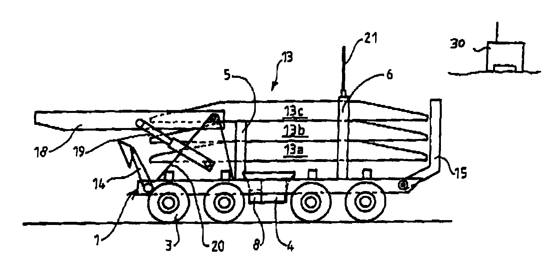
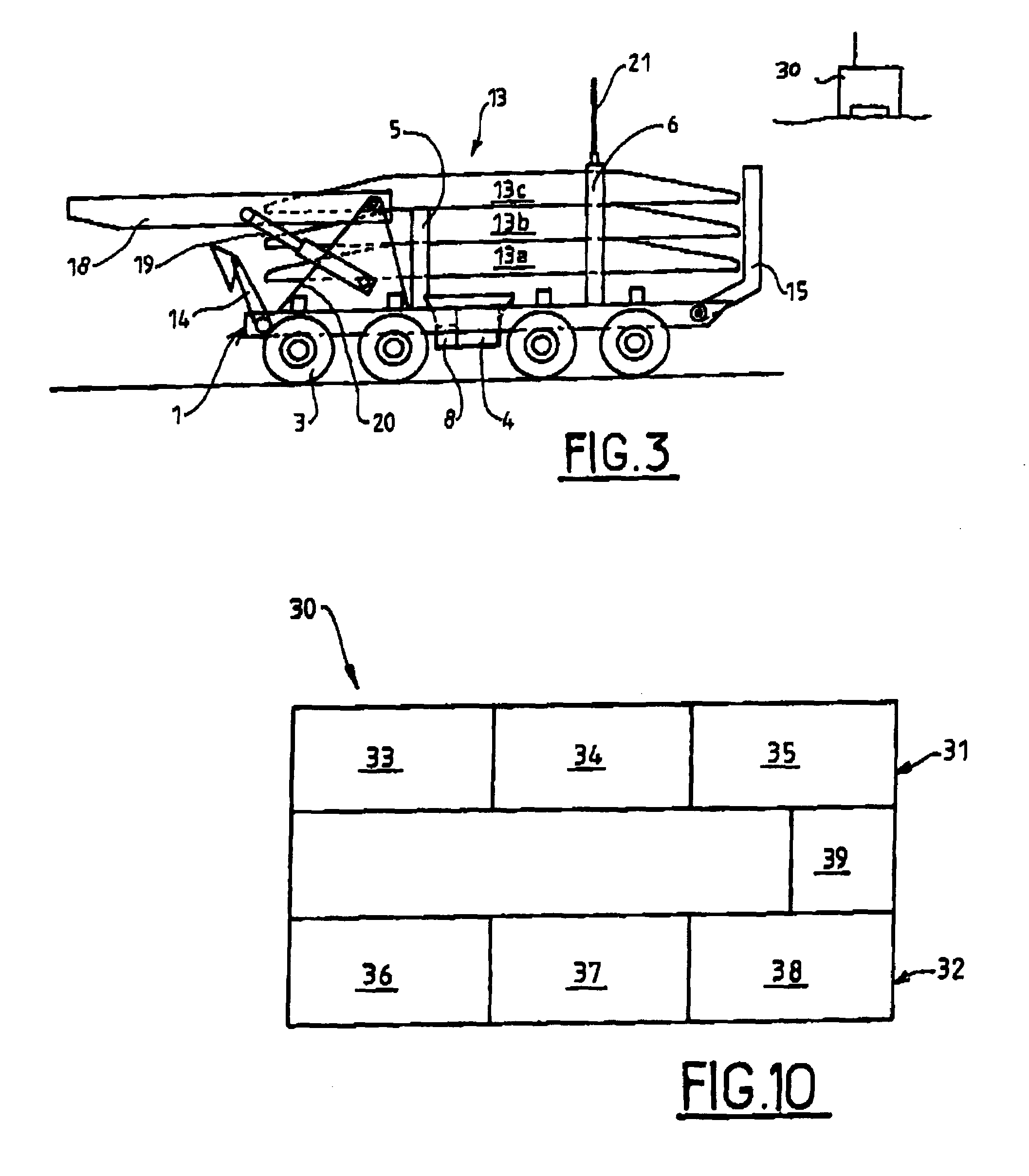
The present invention provides a bridge laying system that only requires light, autonomous, remote-controlled means. The system includes a vehicle for carrying the bridge and a control post for controlling the vehicle. The vehicle is unmanned and armor-free, and it is motorized for autonomy over any terrain at a distance from the control post. The vehicle may be tracked or wheeled, or a combination of both. It also includes means to implement the bridge and control means able to be actuated at a distance from the control post. The communication means may be of various types such as fixed, ultrasound, sound, luminous beam, infrared link, or radio wave. The invention provides safety for the crew, simplifies the design and production of the platform, and allows for the use of commercially-available components.

Problems solved by technology

It is thus generally a heavy and cumbersome vehicle, difficult to manoeuvre and only able to be used in zones of relatively easy access.

Method used


Image

  • System for bridge-laying
  • System for bridge-laying
  • System for bridge-laying

Examples


Embodiment Construction

[0027]Bridge carrying vehicles currently used in the army are constituted by a self-propelled chassis with a crew of at least two. The protection constraints for the on-board crew generate masses of around 60 tons for a tracked vehicle and 50 tons for a wheeled vehicle. It is easy to understand that such vehicles require substantial motorization.

[0028]Both the mass and the high level of performance and cross-country mobility required means that in the design of these vehicles, specific components have to be created. Moreover, since the need for this type of equipment is not great, the production of new equipment is ruled out.

[0029]FIG. 1 shows a side view of a platform 1 in the form of a vehicle composed of a chassis 2 motorized by eight wheels 3 (3a to 3d). A heat engine 4, of the diesel type, makes this platform mobile. As described previously, it goes without saying that the engine 4 enables the platform to be positioned as near as possible to the intervention site and makes it m...


PUM


Abstract

A system to lay a bridge between two banks, wherein said system firstly comprises a bridge carrying vehicle constituted by a remote-controlled self-propelled platform incorporating means to deploy and retract said bridge, said platform being unmanned and armor-free, and secondly a control post comprising means to communicate with said platform.

Description

BACKGROUND OF THE INVENTION[0001]1. Field of the Invention[0002]The technical scope of the present invention is that of systems enabling the deployment of a modular bridge carried by a vehicle, able to be deployed over an obstacle to allow vehicles to get across.[0003]2. Description of the Related Art[0004]To cross a river, a ford or a ditch, it is well known to use a vehicle carrying girders that are to be deployed over the obstacle. The vehicle is namely equipped with means enabling the bridge to be deployed, motorization ensuring its autonomy on the field of operations and means reinforcing its resistance to attacks by various projectiles. It is thus generally a heavy and cumbersome vehicle, difficult to manoeuvre and only able to be used in zones of relatively easy access.[0005]By way of example, reference may be made to French patents 2 637 300, 2 637 301, 2 731 447 and 2 731 448 in the name of the applicant.[0006]All the bridges illustrated by these patents are generally carri...

Claims


Application Information

Patent Timeline
Patent Type & Authority Patents(United States)
IPC IPC(8): E01D15/127E01D15/22
CPCE01D15/127
Inventor BERTRANDCHASSILLAN, MARCCHAPOUTHIER, BENO T
Owner NEXTER SYST SA
Learn More