
Multi-rate and multi-level gigabit interface converter

a converter and multi-level technology, applied in electromagnetic transmission, electrical equipment, transmission, etc., can solve the problems of inability to interoperate with a low power transceiver, inability to interoperate with a high data rate and low data rate prior art transceiver modules, and inability to transmit and receive data within a limited range. , to achieve the effect of simplifying supply chain management and reducing the number of different modules

Active Publication Date: 2007-02-06
II VI DELAWARE INC
View PDF7 Cites 16 Cited by
  • Summary
  • Abstract
  • Description
  • Claims
  • Application Information

AI Technical Summary

Benefits of technology

[0007]A multilevel and multirate transceiver module has been designed that can operate at multiple transmitter and receiver power ranges which are selected in accordance with an input signal. In an embodiment, the transceiver module operates at two distinct levels: (1) from −3 dBm to −9 dBm, and (2) −9 dBm to −15 dBm. In this manner, the transceiver module of the present invention interoperates with other transceiver modules such as GBICs that transmit or receive data over a power range from −3 dBm to −15 dBm. These ranges allow the transceiver module of the present invention to interoperate with modules that utilize laser 132 as well as LED based transmitters and respective receivers 131.
[0008]The multilevel and multirate transceiver module of the present invention provides further advantages by simplifying supply chain management for a transceiver module user because the transceiver module of the present invention reduces the number of different modules that must be kept in inventory.

Problems solved by technology

Each transceiver module can only transmit and receive data within a limited range of power levels.
Such a GBIC, however, does not interoperate with a low power transceiver such as an Agilent HFBR-5204 that typically receives power levels up to −14 dBm.
For these and other reasons, the high data rate and low data rate prior art transceiver modules do not interoperate.

Method used


Image

  • Multi-rate and multi-level gigabit interface converter
  • Multi-rate and multi-level gigabit interface converter
  • Multi-rate and multi-level gigabit interface converter

Examples


Embodiment Construction

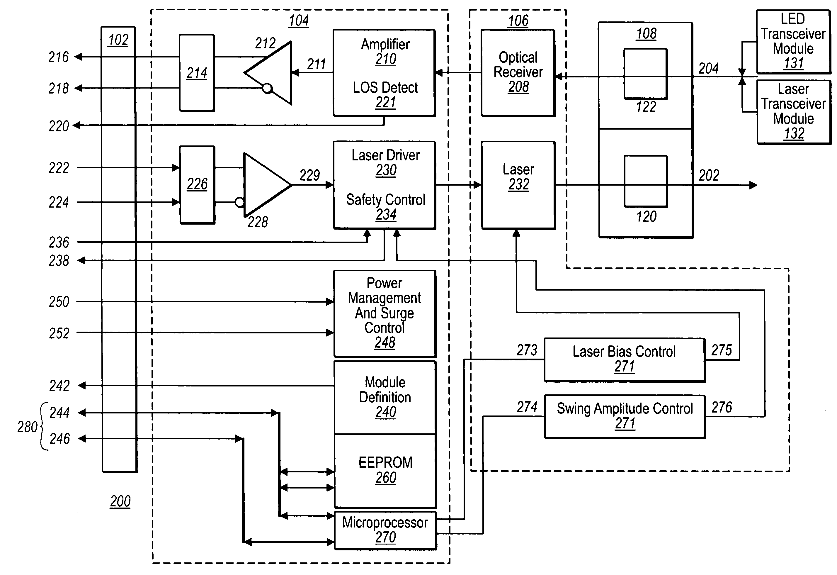
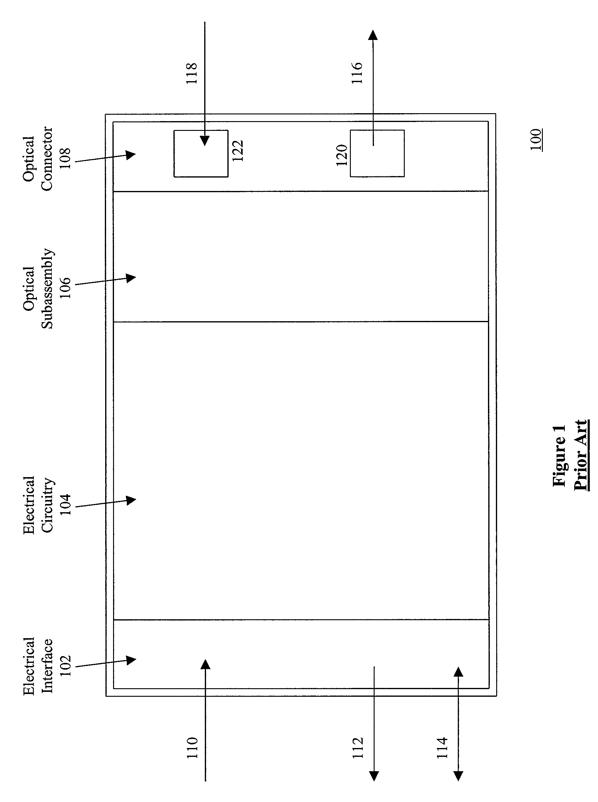
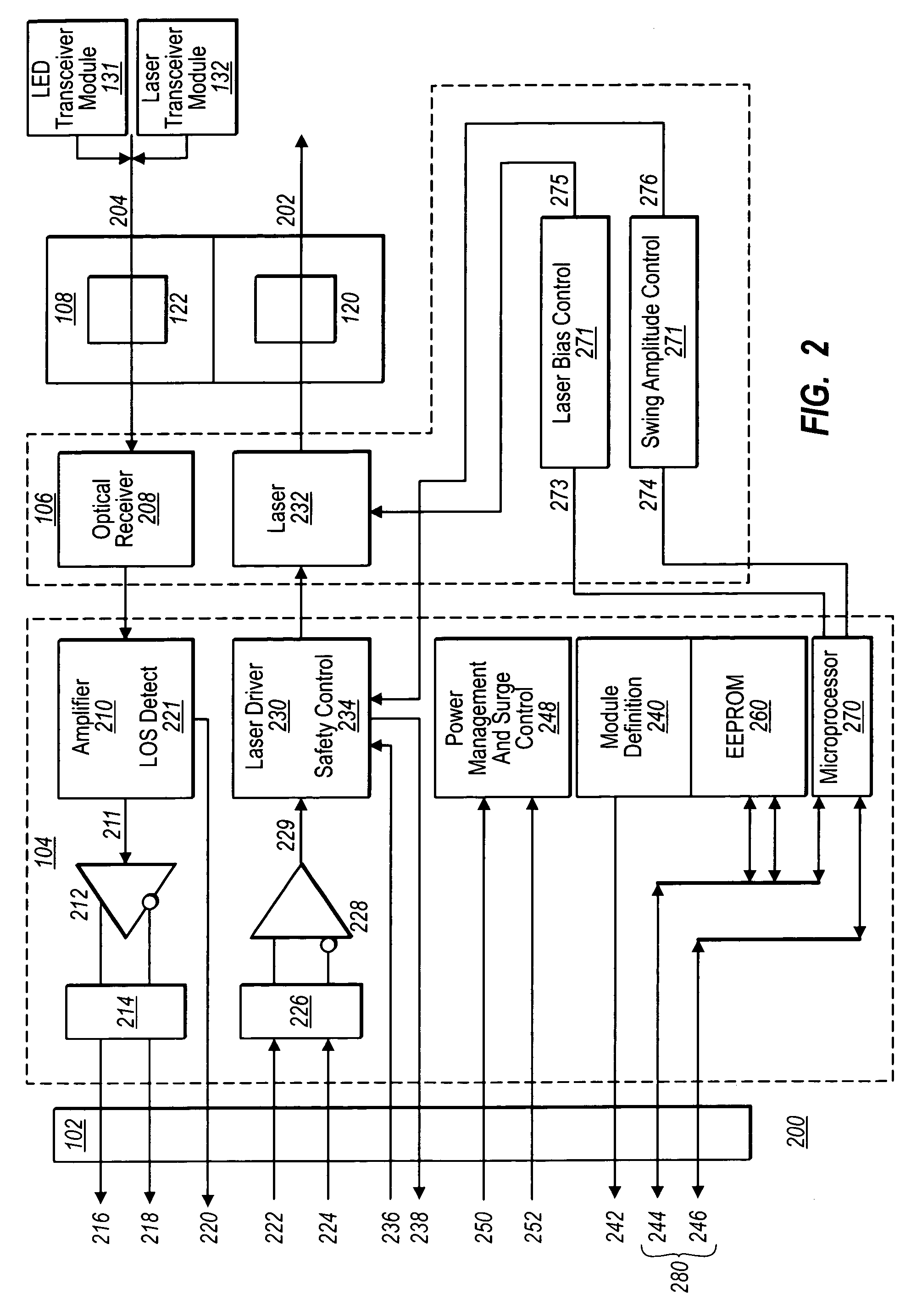
[0024]FIG. 2 is a block diagram of transceiver module 200 according to an embodiment of the invention. As shown in FIG. 2, duplex communication with another transceiver module or a GBIC is achieved through optical transmit signal 202 and optical receive signal 204. In receiving optical receive signal 204 from another transceiver module or GBIC, typically carried on fiber optic cable, the optical receive signal 204 is coupled to optical connector 108 which is in turn coupled to optical receiver 208. Optical receiver coupler 122 is typically an optical fiber connector. The optical signal is converted into a low level electrical signal 209 by optical receiver 208. For proper operation, however, the low level electrical signal is coupled to amplifier 210 to generate a high level electrical signal 211 which is coupled to PECL driver 212 and termination 214 to generate differential PECL signals +RX_DAT 216 and −RX_DAT 218. PECL signals +RX_DAT 216 and −RX_DAT 218 are then coupled to elect...


PUM


Abstract

This disclosure is concerned with optoelectronic modules. In one example, an optoelectronic transceiver includes a data transmit line coupled to an optical source, and a data receive line coupled to an optical detector. In addition, a serial bus is provided that is distinct from both the data transmit line and the data receive line. A microprocessor is coupled to the serial bus and corresponds to a serial address. Finally, an optical driver of the optoelectronic transceiver is coupled to the optical source, and the microprocessor provides a control signal for adjusting a swing amplitude of the optical driver in accordance with one or more commands received by the microprocessor via the serial communication bus.

Description

FIELD OF THE INVENTION[0001]The present invention relates generally to optoelectronic communication modules and, more specifically, to communication modules that can inter-operate with modules that transmit or receive data at various data rates.BACKGROUND OF THE INVENTION[0002]In 1990, a group of member companies formed the Small Form Factor (SFF) Committee as an ad hoc group to address storage industry needs. In 1992, the objectives of the SFF Committee were broadened to encompass other areas such as pinouts for interface applications and form factor issues. The SFF Committee is now a forum for resolving industry issues that are either not addressed by the standards process or need an immediate solution.[0003]On Sep. 27, 2000, the SFF Committee published its Proposed Specification for GBIC (Gigabit Interface Converter), Rev. 5.5 (hereafter referred to as the “GBIC Specification”). The specification describes the GBIC for Fiber Channel applications applicable to systems manufacturer...

Claims


Application Information

Patent Timeline
Patent Type & Authority Patents(United States)
IPC IPC(8): H04B10/00H04B10/02
CPCH04B10/801
Inventor WEBER, ANDREAS
Owner II VI DELAWARE INC
Learn More