Transmitting apparatus using multiple lambda source in WDM network

a technology of wavelength division multiplexing and transmitter, applied in electromagnetic transmission, multi-component communication, wavelength-division multiplexing systems, etc., can solve the problems of tunable laser sources, high cost of transmitters, and complex design, so as to reduce time delay, minimize costs and efforts, and improve the effect of structur

Inactive Publication Date: 2007-02-06
SAMSUNG ELECTRONICS CO LTD
View PDF4 Cites 2 Cited by
  • Summary
  • Abstract
  • Description
  • Claims
  • Application Information

AI Technical Summary

Benefits of technology

[0016]Accordingly, the present invention has been made to solve the above-mentioned problems of the prior art devices. It is also an object of the present invention is to provide a transmitting apparatus using a multiple lambda source in WDM network having an improved structure to minimize costs and efforts and reduce time delay that may be incurred through wavelength shift by reducing some of the expensive parts required in prior art systems.

Problems solved by technology

However, because this transmitting apparatus needs a wavelength converter for each channel and a laser diode for providing tuned wavelengths required in wavelength conversion for the operation of each wavelength converter, such a transmitting apparatus is very expensive.
Further, because too many components are necessary for constructing this transmitting apparatus, the design is very complicated.
However, the tunable laser source has several drawbacks, including the fact that it is very expensive and has a relatively low response speed.
Further, the delay time of the tunable laser source is added to the switching time, thereby further increasing the response time of the tunable laser source.
Accordingly, the tunable laser source is not suitable for a transmitting part of an optical cross-connector which requires a high speed of conversion.

Method used


Image

  • Transmitting apparatus using multiple lambda source in WDM network
  • Transmitting apparatus using multiple lambda source in WDM network
  • Transmitting apparatus using multiple lambda source in WDM network

Examples


Embodiment Construction

[0024]Hereinafter, preferred embodiments according to the present invention will be described with reference to the accompanying drawings. For the purposes of clarity and simplicity a detailed description of known functions and configurations incorporated herein will be omitted as it may make the subject matter of the present invention unclear.

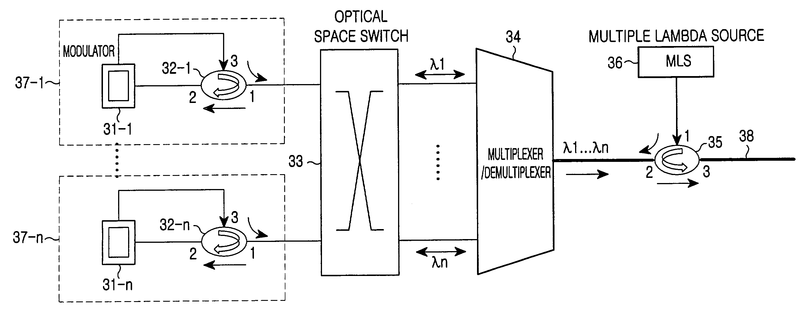
[0025]FIG. 3 shows a transmitting apparatus in accordance with one embodiment of the present invention that uses a multiple lambda source in a WDM network.

[0026]As shown in FIG. 3, a transmitting apparatus of a WDM network uses a multiple lambda source 36 introduces a multiple lambda source in tandem with a multiplexer / demultiplexer 34. The transmitting apparatus demultiplexes the multiple lambda source through optical path circulation. The transmitting apparatus modulates each channel by connecting the multiple lambda source through an optical space switch 33 to channel cards according to their wavelengths. Then, the modulated channels pass t...


PUM


Abstract

A transmitting apparatus using a multiple lambda source in WDM network, which has an improved structure to minimize costs and efforts and reduce time delay that may be incurred through wavelength shift. The transmitting apparatus comprises: a multiple lambda source providing a signal with multiple wavelengths, which carries no information; a first optical circulator for transferring the signal with multiple wavelengths carrying no information, which has been transmitted from the multiple lambda sources, to multiplexer / demultiplexer, the first optical circulator transferring a multiplexed signal from the multiplexer / demultiplexer. The multiplexer / demultiplexer demultiplexes the multiple wavelength optical signal from the first optical circulator and for multiplexing optical signals of each wavelength on which information is loaded. An optical space switch for line-distributing demultiplexed signals from the multiplexer / demultiplexer to a channelization module according to each wavelength of the demultiplexed signals, and for transferring optical signals from the channelization module to the multiplexer / demultiplexer; and the channelization module for modulating line distributed optical signals from the optical space switch to generate modulated optical signals, and for transferring the modulated optical signals to the optical space switch.

Description

CLAIM OF PRIORITY[0001]This application claims priority to an application entitled “Transmitting apparatus using multiple lambda source in a WDM network,” filed in the Korean Intellectual Property Office on Dec. 20, 2002 and assigned Serial No. 2002-81694, the contents of which are hereby incorporated by reference.BACKGROUND OF THE INVENTION[0002]1. Field of the Invention[0003]The present invention relates to a transmitting apparatus using a multiple lambda source in a Wavelength Division multiplexing (WDM) network. More particularly, the present invention relates to a transmitting apparatus using a multiple lambda source in a WDM network. The multiple lambda source has an improved structure enhancing the performance of the transmitting apparatus, and has the potential of unify standards of subsystems.[0004]2. Description of the Related Art[0005]In the field of very high-speed optical communication, Wavelength Division multiplexing (WDM) that utilizes a plurality of optical channels...

Claims


Application Information

Patent Timeline
Patent Type & Authority Patents(United States)
IPC IPC(8): H04J14/02H04J14/00H04B10/27H04B10/291H04B10/54H04B10/572
CPCH04J14/02H04B10/506
Inventor SHIN, HONG-SEOKHWANG, SEONG-TAEKOH, YUN-JE
Owner SAMSUNG ELECTRONICS CO LTD
Why Eureka
Try Eureka