
Optical channelizer utilizing resonant microsphere coupling

Inactive Publication Date: 2007-02-06
HRL LAB
View PDF29 Cites 15 Cited by
  • Summary
  • Abstract
  • Description
  • Claims
  • Application Information

AI Technical Summary

Benefits of technology

[0010]An object of the present invention is to provide a method and apparatus for converting optical channels in an OWDM network to wireless channels that may be radiated in free-space, in which the wireless channels have a one-to-one correspondence with the optical channels. It is a further object of the present invention to provide for conversion of the optical channels to wireless channels with a system that is small and inexpensive.

Problems solved by technology

Such a system has an advantage of being easily implemented, but a major disadvantage is the limited number of optical channels that can be carried.
DOWDM systems provide substantially more channels than a sparse system, but are also more complex and difficult to implement.
OWDM networks provide the capability to transmit large amounts of data between locations, but they have a fundamental limitation.
Hence, OWDM networks may not serve areas where installation and maintenance of optical fiber is difficult and expensive.
These areas may comprise rural areas where there are few users and these users are separated by significant distances, making the provision of fiber uneconomical.
These areas may also include densely populated urban areas where the costs of interfering with the infrastructure and providing OWDM fiber to multiple locations may be prohibitively expensive.
Coupling the separate OWDM networks through the use of OWDM fiber has the difficulty and expense factors discussed above.
Non-WDM data links (such as radio frequency links or telephone lines) can be provided at a lower cost, but the networking capabilities inherent in a WDM network are lost.
However, the generation of low phase noise signals at microwave or millimeter wave frequencies using standard electrical frequency synthesizers may be a costly process, since several multiplication stages of a high quality, low frequency signal to the microwave or millimeter wave frequencies are required.
Also, frequency synthesizers capable of this task can be quite bulky.
Therefore, as the number of channels in the OWDM system, and hence in the converted wireless link, increases, the use of standard electrical frequency synthesizers to provide the required conversion can become detrimental in terms of cost and size.

Method used


Image

  • Optical channelizer utilizing resonant microsphere coupling
  • Optical channelizer utilizing resonant microsphere coupling
  • Optical channelizer utilizing resonant microsphere coupling

Examples


Embodiment Construction

[0031]The present invention will now be described more fully hereinafter with reference to the accompanying drawings, in which preferred embodiments of the invention are shown. This invention may be embodied in many different forms and should not be construed as limited to the embodiments set forth herein. Specifically, while the embodiments described below present examples of systems or subsystems having a single channel or four channels, the present invention is not limited to single channel or four channel embodiments.

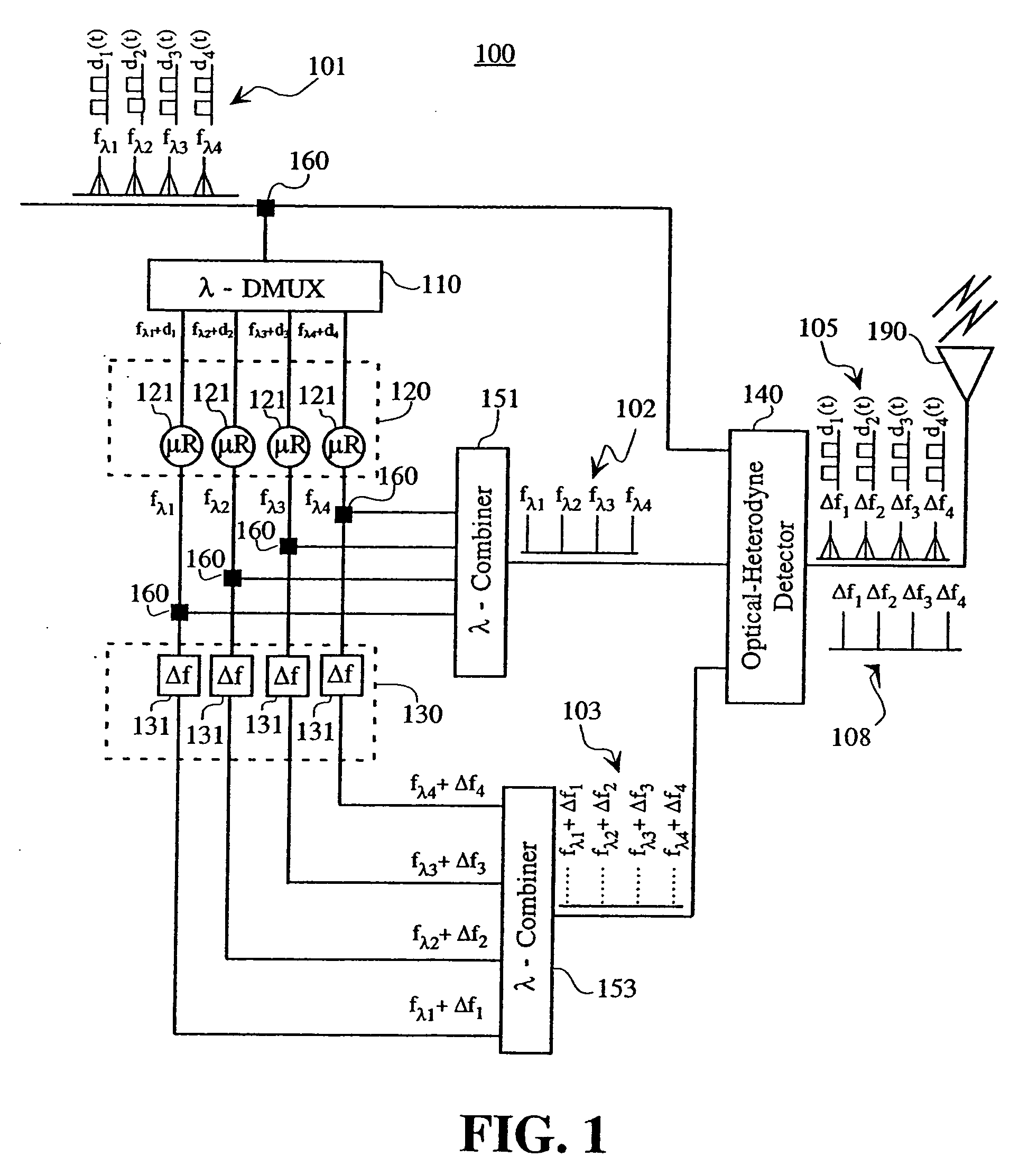
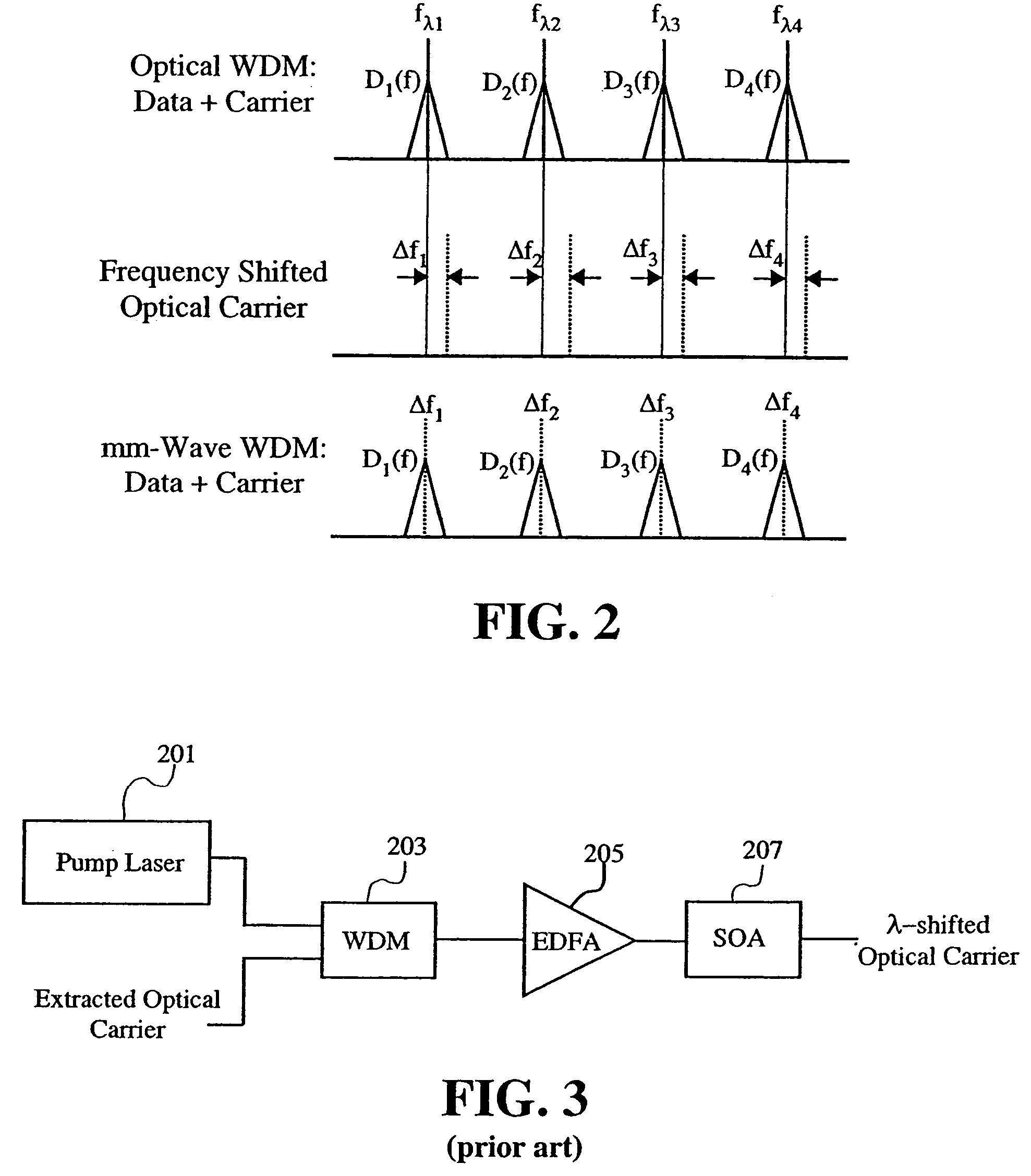
[0032]A block diagram of an optical frequency to wireless frequency converter system 100 according to the present invention is shown in FIG. 1. The system 100 receives a composite OWDM network optical signal 101 containing multiple optical channels in which each optical channel has a different optical carrier frequency. The spectrum of the composite optical signal 101 with four optical channels is shown in FIG. 1. Each optical channel contains an optical carrier sig...


PUM


Abstract

In a method and apparatus for converting optical wavelength division multiplexed channels to wireless channels, the information carrying optical carriers are first de-multiplexed and each optical carrier is then extracted from the data using an optical channelizing technique. The optical frequency of each of the extracted optical carriers is then shifted by an amount equal to the desired wireless carrier frequencies in the broadband wireless channels. Optical heterodyning of the frequency-shifted extracted lightwave carriers with the original data-containing optical signals, which are mutually in phase coherence, in a photodetector results in a set of wireless carriers each modulated with the data carried by the corresponding optical channel.

Description

[0001]This patent application is divisional application of U.S. application Ser. No. 09 / 897,713, filed on Jun. 29, 2001 (now U.S. Pat. No. 6,778,318). This patent application is related to U.S. Patent application Ser. No. 10 / 873,897 filed on Jun. 29, 2001, which is another divisional application of U.S. patent application Ser. No. 09 / 897,713.FIELD OF THE INVENTION[0002]The present invention relates to converting optical data signals to radio frequency data signals. More specifically, the present invention relates to converting broadband data transmitted on optical carriers in conventional wavelength-division-multiplexed (WDM) networks to corresponding microwave or millimeter wave carriers that support the continued broadband transmission of the data.BACKGROUND OF THE INVENTION[0003]Wavelength Division Multiplexing (WDM) is a basic technology of networking optical signals. It is a technique by which a single fiber is used to carry many separate and independent optical channels. Each ...

Claims


Application Information

Patent Timeline
IPC IPC(8): G02B6/26G02B6/28H04B10/12H04B10/148
CPCH04B10/25752H04B10/64H04B10/60
Inventor SAYYAH, KEYVANIZADPANAH, HOSSEINPEPPER, DAVID M.
Owner HRL LAB
Learn More