
Miniature LED flashlight having split ring

a technology of led flashlights and light sources, applied in the field of miniature led flashlights, can solve the problems of reducing the mobility required of law enforcement personnel, difficulty and cumbersome for law enforcement personnel to carry, and the bulky and cumbersome nature of led flashlights

Inactive Publication Date: 2007-02-06
ARMAMENT SYST & PROCEDURES
View PDF7 Cites 8 Cited by
  • Summary
  • Abstract
  • Description
  • Claims
  • Application Information

AI Technical Summary

Benefits of technology

The solution provides a compact, reliable, and easily producible flashlight that can be automatically activated, reducing fatigue on the LED leads and increasing manufacturing efficiency, while allowing hands-free operation and customization.

Problems solved by technology

With such a large number of items, it is often difficult and cumbersome for law enforcement personnel to carry all of these items on their person so they can be accessed.
Flashlights of this type are often bulky and cumbersome.
However, the inconvenient size and weight of conventional flashlights reduce the mobility of law enforcement personnel required to carry such flashlights along with other law enforcement equipment.
As a result, the flashlight may purposefully or inadvertently be left, presenting a problem when the need for a flashlight arises and the officer does not have one readily available.
Even small conventional flashlights, however, can be cumbersome and inconvenient to carry for this purpose.
However, no known lightweight LED flashlights are readily adapted to be actuated when selectively inserted into a case or carrier, that in turn is adapted to be attached to the user's person, such as to a hat brim or backpack.
This results in increased fatigue on the LED leads, and adversely affects switch reliability.
In addition, many small flashlights are constructed with hard plastic outer shells unsuitable for marking, etching, or interchanging.
Other small flashlights may include an integral clip for attachment to clothes, baggage, or keys, but they generally have spring-biased locking mechanisms, which are vulnerable to breakage and typically require extra parts and expense in manufacturing.
Further, most flashlights require at least partial human assembly, which is a relatively labor-intensive process and expensive.
Complete automation of the assembly process would significantly reduce human error inherent in flashlight assembly, significantly increase the number of lights able to be produced in a given period of time, and greatly lower the price per unit.
Such devices, however, typically use incandescent bulbs and dry cell batteries.

Method used


Image

  • Miniature LED flashlight having split ring
  • Miniature LED flashlight having split ring
  • Miniature LED flashlight having split ring

Examples


Embodiment Construction

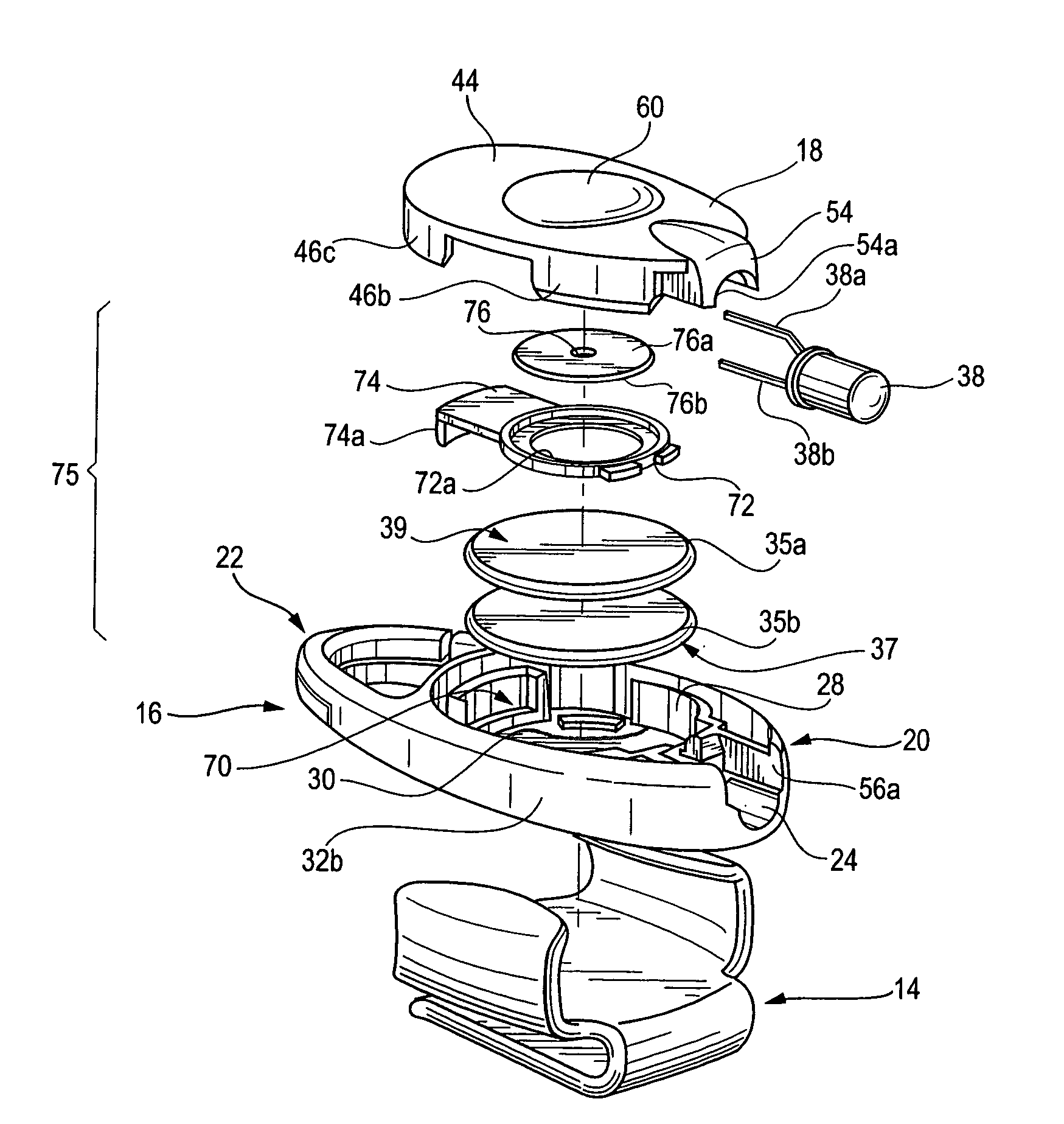
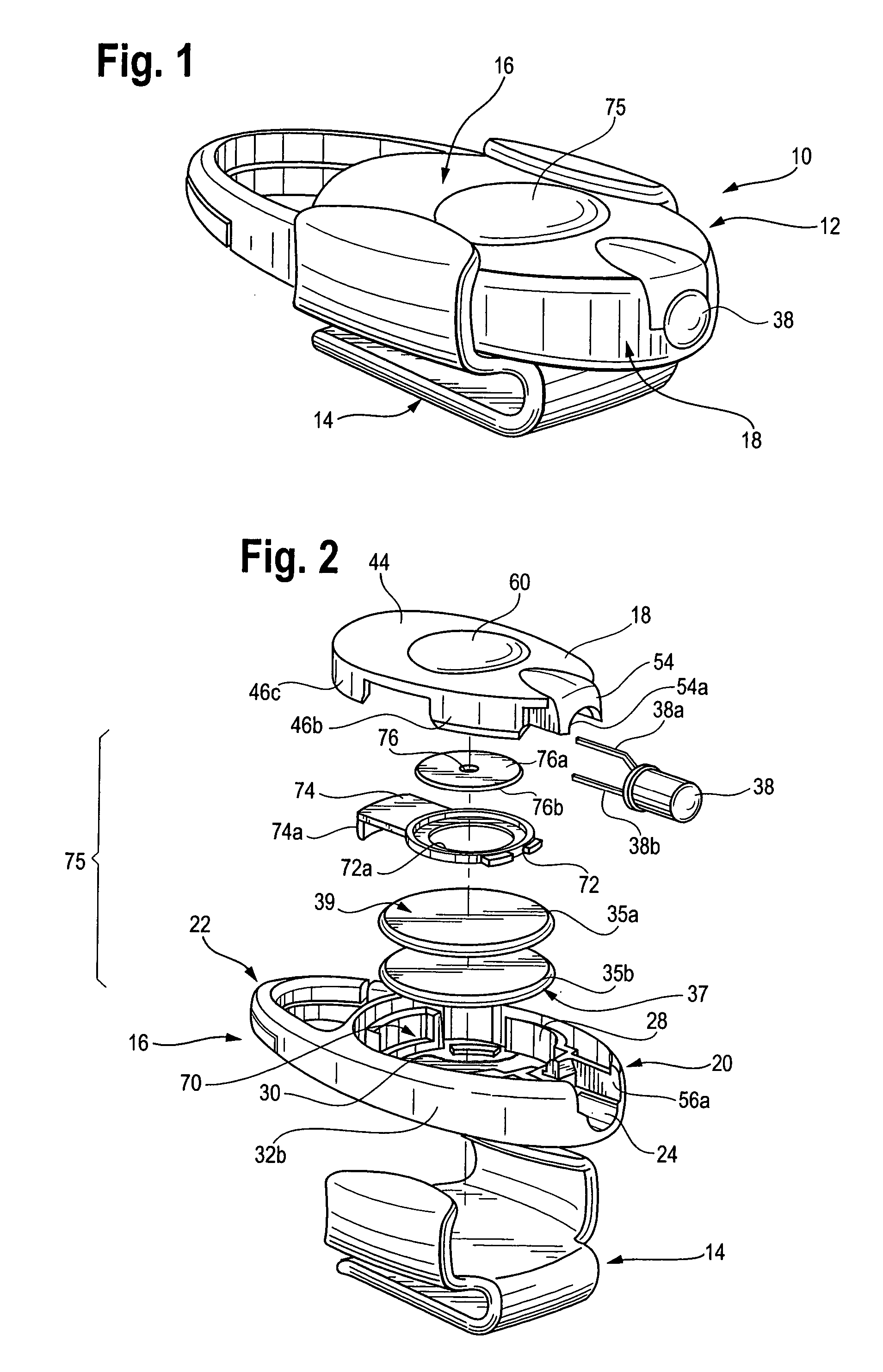
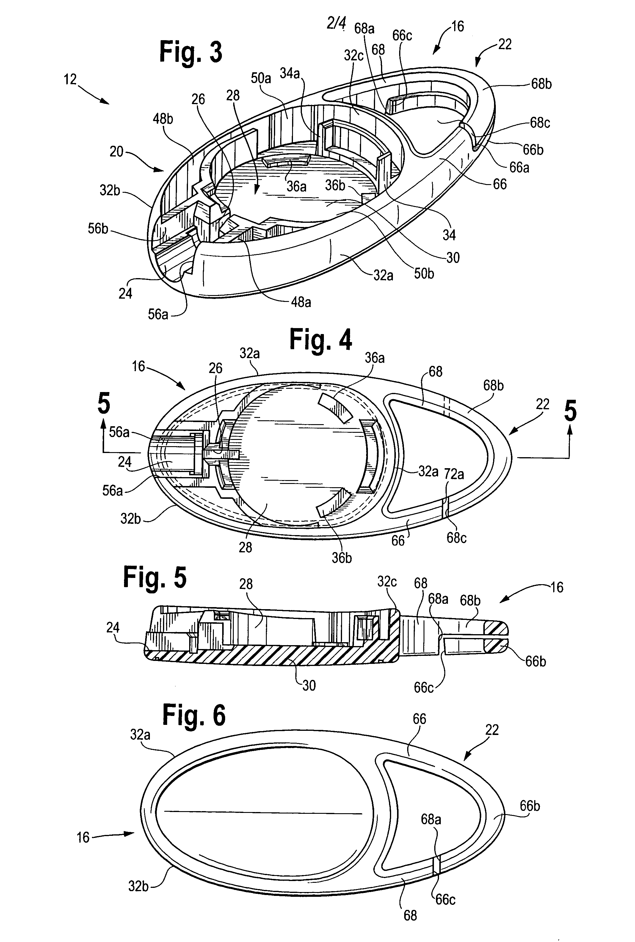
[0030]Referring now to the FIGS. 1 and 2, a miniature flashlight assembly 10 is shown for attachment to a support, such as an article of clothing or baggage, constructed in accordance with the principles of the present invention. The flashlight assembly 10 includes a miniature flashlight 12 and a mating flashlight case or carrier 14. Attaching the flashlight 12 and case 14 to a support, such as a user's hat brim, allows direction of a light beam toward a specific location, leaving both of the user's hands free for other uses. Preferably, the flashlight 12 has an overall longitudinal length of approximately 2 inches, a traverse width of approximately 0.95–1.0 inch, and a maximum transverse thickness of approximately ⅜ inch. The flashlight 12 preferably uses a light emitting diode (LED) 38 as a light source and a pair of coin-type 3-volt batteries 35a and 35b as a power source. A momentary contact switch 75, to be described, preferably activates the LED.

[0031]The flashlight 12 is adap...


PUM


Abstract

A flashlight includes a light emitting diode, power source, momentary contact switch for manually activating the flashlight, and a split-ring clip for attachment to key-rings, baggage, and various articles of clothing. The flashlight body includes an interchangeable bottom wall, suitable for engraving, printing, silk screening, or stamping.

Description

BACKGROUND OF THE INVENTION[0001]The present invention relates generally to flashlights, and more particularly to a miniature flashlight having a light emitting diode (LED) light source that is useful for law enforcement personnel and civilians alike.[0002]Conventional general-purpose flashlights are well known in the art and have often been used by law enforcement personnel in the execution of their duties and in emergency situations. Flashlights are used for a wide variety of purposes. For example, they are often used during traffic stops to illuminate the interior of a stopped vehicle or to complete a police report in the dark. They are also used to facilitate searches of poorly lit areas, and may be used to illuminate dark alleys or stairwells. Law enforcement personnel also use flashlights to check or adjust their equipment when positioned in a darkened area or at night, and may also be used to send signals to one another. Consequently, it is common, and frequently required, fo...

Claims


Application Information

Patent Timeline
Patent Type & Authority Patents(United States)
IPC IPC(8): F21L4/00A44B15/00F21L4/02F21V21/088F21V23/04
CPCA44B15/005F21L4/027F21V23/0414F21V21/0885F21Y2101/02F21Y2115/10
Inventor PARSONS, KEVIN L.
Owner ARMAMENT SYST & PROCEDURES
Learn More