
System and method for regenerative PWM AC power conversion

a technology of pwm and ac power conversion, which is applied in the direction of dc-ac conversion without reversal, dc source parallel operation, transportation and packaging, etc., can solve the problems of internal diode rectifier not allowing power to flow, especially the effect of traits

Inactive Publication Date: 2007-01-30
BIXEL PAUL S
View PDF3 Cites 61 Cited by
  • Summary
  • Abstract
  • Description
  • Claims
  • Application Information

AI Technical Summary

Benefits of technology

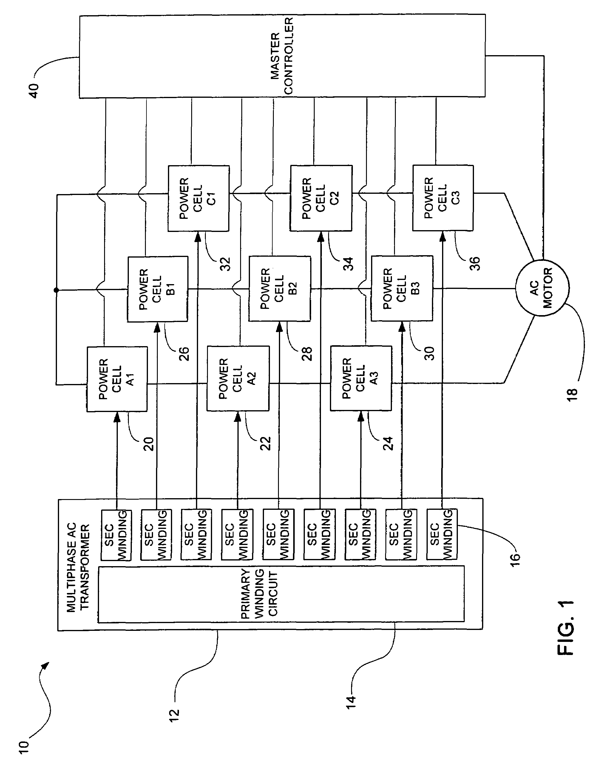
[0007]As exemplified by the drive disclosed in the '545 patent, it is possible to produce a medium-voltage controller with low-voltage power cells by connecting multiple cells in series on each phase output line. Serial connection of cells makes multiple voltage states per phase possible; these multiple voltage states per phase may be used to obtain improved waveforms.

Problems solved by technology

These traits are especially problematic at higher power levels typical for medium voltage motor drives.
The techniques disclosed in the '545 patent are limited in that they provide a motor drive that cannot be used in a regenerative operation mode; i.e., a mode in which power flows from the motor through the drive to the transformer.
Failure to control the power flow would lead to an overvoltage situation developing within the power cell since the power cell has no means to dispose of power from the motor.
The internal diode rectifier does not permit power to flow back to the AC mains connected to the drive.

Method used


Image

  • System and method for regenerative PWM AC power conversion
  • System and method for regenerative PWM AC power conversion
  • System and method for regenerative PWM AC power conversion

Examples


Embodiment Construction

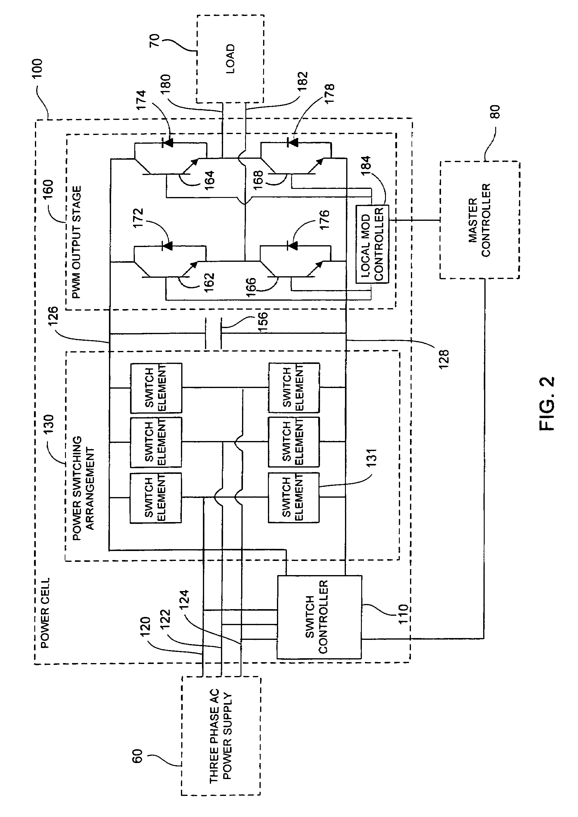
[0021]The present invention provides a multiphase AC power conversion methodology for use in power conversion systems configured for driving an AC motor. The power conversion methodology uses power conversion cells that may be configured to operate in both motoring and regenerative operation modes. In addition to the power cells, the power conversion systems of the invention comprise a multiphase transformer configured to supply multiphase power to each power cell. The transformer may comprise one or more primary windings driving a plurality of secondary windings, each secondary winding being used to power a single power cell, which, in turn, provides single phase AC power to a load such as an AC motor. Multiple power cells having the same output phase may be connected in series to achieve the desired voltage level to be supplied to the load. The voltage provided by each power cell may be controlled using a modulation controller that is connected to each of the power cells.

[0022]The...


PUM


Abstract

A power conversion system for driving a load is provided. The power conversion system comprises a power transformer having at least one primary winding circuit and at least one secondary winding circuit, the primary winding circuit being electrically connectable to an AC power source. The system further comprises at least one power cell, each of the at least one power cell having a power cell input connected to a respective one of the at least one secondary winding circuit. Each power cell also has a single phase output connectable to the load. A power switching arrangement including at least one power switch is connected to the power cell input and a DC bus, and a switch controller is connected to the power switching arrangement and the power cell input. The power cell also has a PWM output stage having a plurality of PWM switches connected to the DC bus and the single phase output. A local modulation controller is connected to the PWM output stage. The switch controller is adapted for monitoring and controlling a DC bus voltage according to a predetermined control methodology in both a motoring mode in which power from the AC power source is supplied to the load by the at least one power cell and a regeneration mode in which power from the load is supplied to the AC power source by the at least one power cell. The power conversion system also comprises a master controller in communication with the switch controller and the local modulation controller of each of the at least one power cell. The master controller is connectable to the load to monitor power flow thereto.

Description

BACKGROUND OF THE INVENTION [0001]The present application is a continuation of U.S. application Ser. No. 10 / 387,368, filed Mar. 12, 2003 now U.S. Pat. No. 6,847,531, which is a continuation-in-part of U.S. application Ser. No. 09 / 683,422 filed Dec. 27, 2001 now U.S. Pat. No. 6,542,390, which derives priority from U.S. application Ser. No. 60 / 258,820 filed Jan. 2, 2001, all of which are incorporated herein by reference in their entirety.[0002]The present invention relates generally to controlling or driving alternating current (AC) motors. More particularly, the present invention relates to a method and apparatus for providing regenerative control of AC motors.[0003]A wide variety of AC medium-voltage variable speed drives for induction motors are known which use a variation of current source topology with a phase-controlled silicon controlled rectifier (SCR) input stage and a 6-pulse or 12-pulse output. This topology may sometimes have the drawbacks of harmonic line currents, a vari...

Claims


Application Information

Patent Timeline
Patent Type & Authority Patents(United States)
IPC IPC(8): H02M7/00H02J7/00H02M5/458H02M7/49H02M7/797H02P23/06
CPCH02M5/4585H02M7/49H02P23/06H02M7/797H02M5/4505H02M2007/4835
Inventor BIXEL, PAUL S.
Owner BIXEL PAUL S
Learn More