
Collaborative tablet computer

a tablet computer and collaborative technology, applied in the field of collaborative tablet computers, can solve the problems of redundancy of additional display, essentially the entire hardware of the additional device, and failure to combine the resources of each device, and achieve the effect of maximum potential protection

Inactive Publication Date: 2007-01-30
IBM CORP
View PDF27 Cites 74 Cited by
  • Summary
  • Abstract
  • Description
  • Claims
  • Application Information

AI Technical Summary

Benefits of technology

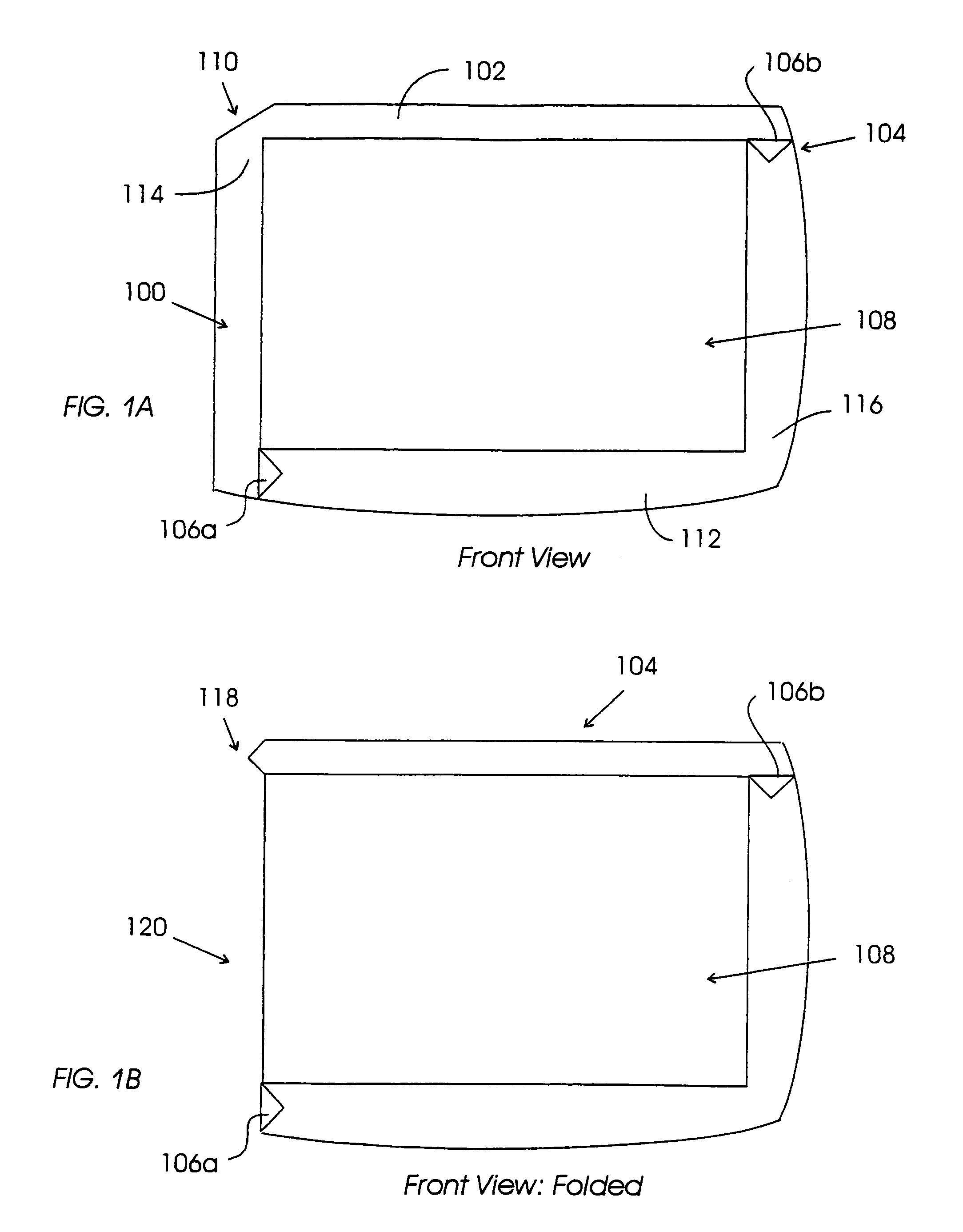
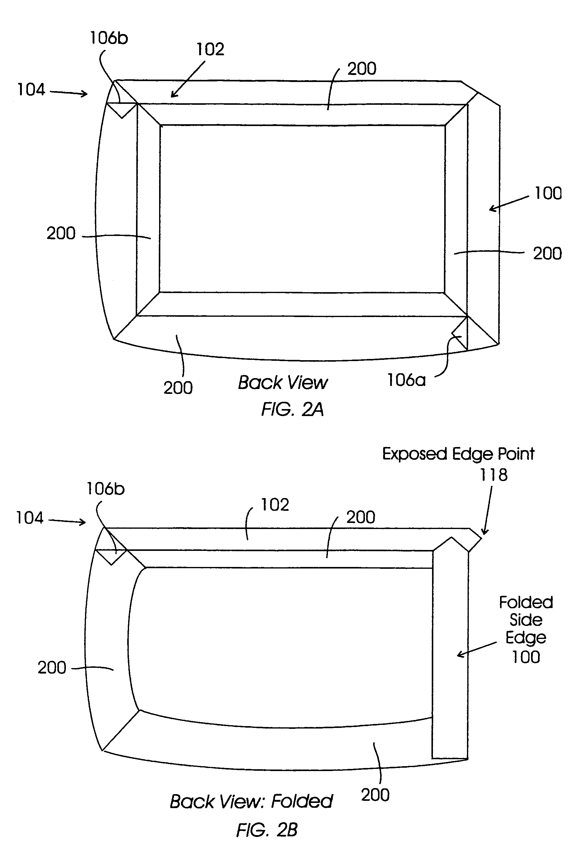
[0011]One embodiment of the present invention allows either, or both, the top edge or side edge of the housing to be simply pivoted underneath the device to expose the edge of the device screen. Electrical and structural connectors are exposed as well. The edges of the device are sharply angled, allowing the edge of the device to pivot under itself without adding any substantial thickness to the device. The two folding side sections are split at a 45 degree angle, allowing for independent rotation of the sections, while still providing the maximum potential protection to the screen edge. When one side is folded down, the other edge extends beyond the screen edge, and therefore must be accommodated for in the mating device with a corresponding cut-out area. These male and female shapes provide the added advantage of a visual cue as to how the two devices connect.

Problems solved by technology

In these cases, the additional display, and essentially the entire hardware of the additional devices, are wasted due to their redundancy.
Significant disadvantages result by failing to combine the resources, such as the displays, of each device in scenarios such as this.
Whatever the precise merits, features and advantages of the above cited references, none of them achieve a collaborative environment wherein a modular display and computing device can be increased and decreased in size and function in response to the task at hand.

Method used


Image

  • Collaborative tablet computer
  • Collaborative tablet computer
  • Collaborative tablet computer

Examples


Embodiment Construction

[0023]While this invention is illustrated and described in a preferred embodiment, the device may be produced in many different configurations, forms and materials. There is depicted in the drawings, and will herein be described in detail, a preferred embodiment of the invention, with the understanding that the present disclosure is to be considered as a exemplification of the principles of the invention and the associated functional specifications of the materials for its construction and is not intended to limit the invention to the embodiment illustrated. Those skilled in the art will envision many other possible variations within the scope of the present invention.

[0024]As part of the present invention a housing / mechanism for a tablet form-factor computing device allows the edge of the device's display to be exposed. Once exposed, the display may be abutted to another like display on a like device to create a larger display meta-device.

[0025]One realization of the present invent...


PUM


Abstract

A section of a housing on a portable computing device is removed or folded away, thereby exposing a free edge of an LCD screen as well as electrical (data and power) connectors and structural connectors. Connectors are placed symmetrically across the exposed edge whereby a male connector on one side mates with a female connector on the other device. Two such devices are physically pushed together, with locking catches securing the two devices together. Upon docking, the two devices recognize the new configuration and re-map the desktop area of the display into a single display for the combined device. In a preferred embodiment, either a top edge or a side edge is selectively exposed independently on the same device, to mate two devices in either a portrait or landscape orientation.

Description

BACKGROUND OF THE INVENTION[0001]1. Field of Invention[0002]The present invention relates generally to the field of “tablet” form-factor digital devices. More specifically, the present invention is related to a modified “tablet” form-factor digital device which can physically “dock” with like devices to create a larger, more capable device.[0003]2. Discussion of Related Art[0004]A tablet form factor is a “single slab” device which generally does not have a hinged keyboard section (in comparison to a notebook computer), but is essentially a screen device with some sort of touch screen as the primary input. Current examples on the market are the Fujitsu “Stylistic” series of tablet computers (representing Win9x devices), and at a smaller scale, Palm Pilot and handheld WinCE devices.[0005]Many times, work utilizing such tablet form factor devices involves two or more people in immediate proximity to each other collaborating on some task which involves the use of such devices. In most c...

Claims


Application Information

Patent Timeline
IPC IPC(8): G09G5/00G06F1/16G06F3/14G06F3/153G09G3/20
CPCG06F1/1626G06F1/1632G06F1/1656Y10S345/903G06F2200/1614G09G2300/026
Inventor KNOPF, ERIC ANDREW
Owner IBM CORP
Learn More