
Device for the coupling of excavator teeth

a technology for coupling and excavators, which is applied in the direction of soil-shifting machines/dredgers, constructions, etc., can solve the problems of increasing local wear and suffering significant problems at the active edge, and achieves greater mechanical strength, increased cross-section of the nose, and increased mechanical strength.

Inactive Publication Date: 2007-01-30
METALOGENIA PATENTES
View PDF54 Cites 94 Cited by
  • Summary
  • Abstract
  • Description
  • Claims
  • Application Information

AI Technical Summary

Benefits of technology

[0009]In order to obtain an improvement in the characteristics of the couplings for excavator teeth, achieving rapidity of assembly and secure and durable coupling between the tooth and the tooth-carrier, the inventor of the present patent application has carried out investigations and tests which have resulted in a coupling for excavator teeth which has an improved performance in use.
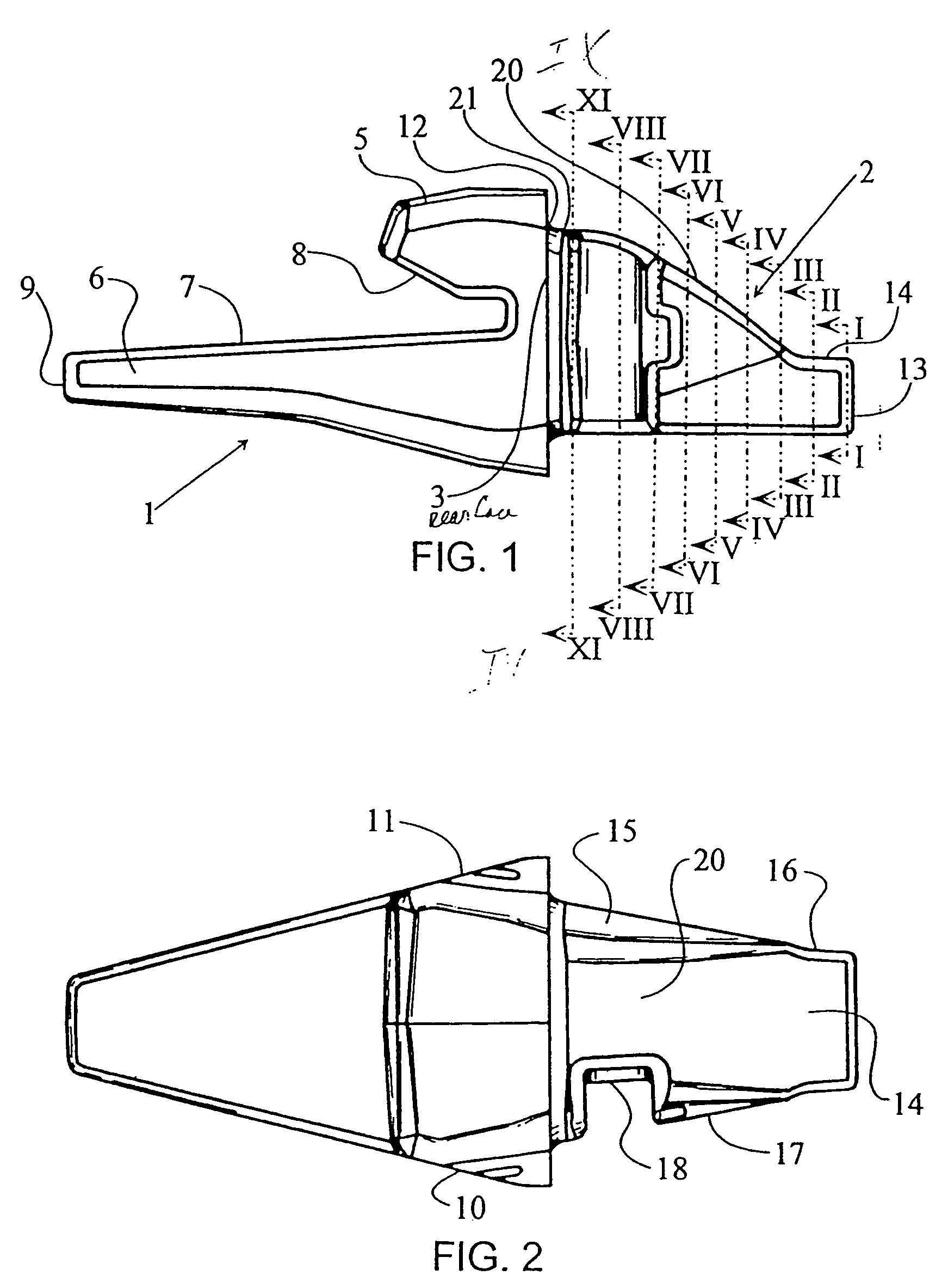
[0011]With this arrangement the result is obtained that the nose of the tooth-carrier exhibits a much higher mechanical strength and, above all, in normal operation thereof no stresses are produced which tend to eject the tooth, which constitutes a recurrent problem of the currently known tooth-carriers. In particular, the slightly curved structure, with the convexity directed outwards, of the upper face of the nose of the tooth-carrier permits, in addition to a very efficient coupling between the tooth and the tooth-carrier, an increase in the cross-section of the nose of the tooth-carrier, and therefore a greater mechanical strength on the latter.
[0012]The device of the present invention is likewise characterized by a new type of cotter pin for retaining the tooth on the tooth-carrier, which is distinguished by its easy introduction and high resistance to removal, basically comprising a body of the cotter pin of flattened generally parallelepipedal structure, which on one of its intermediate sized faces has a wide rebate to which there is joined, by means of vulcanization of a special rubber, an insert carrying a small lateral projection with rounded transverse edges which is intended to be introduced into a seating of complementary shape of the tooth-carrier after its introduction.

Problems solved by technology

The buckets of excavators and the like suffer significant problems at the active edge because of the high degree of wear to which it is subjected by contact with the earth and stones, which have very abrasive characteristics.
The other contradictory characteristic lies in the need for the mounting of the tooth on the tooth-carrier located at the active edge of the bucket for excavators or the like to be effected with sufficient adjustment to avoid as far as possible any play between the facing regions of the tooth-carrier and the tooth, since the occurrence, otherwise inevitable, of play in the said region results in an increase in the stresses at specific points of contact between the tooth and the tooth-carrier, which further increase the wear locally, in a process which may end in breakage of the parts and which involves changing the worn part, that is to say, the tooth, more or less frequently, according to how the above-mentioned wear phenomena can be controlled to a greater or lesser degree.
At present, many types of coupling between the teeth of excavators and the tooth-carriers are known, although all of them, given the contradictory conditions to be fulfilled and the hard work to which said components are subjected, exhibit defects with regard to what could be considered an ideal solution in terms of life of the tooth and avoidance of excessive wear on the tooth-carrier, enabling the latter to have an acceptably extended life.

Method used


Image

  • Device for the coupling of excavator teeth
  • Device for the coupling of excavator teeth
  • Device for the coupling of excavator teeth

Examples


Embodiment Construction

[0020]As shown in the FIG., the coupling for excavator teeth which is the subject of the present invention has a fork-like part 1 intended for coupling with the edge of the excavator bucket and a region 2 that projects from the rear face 3 of the region 1 and is intended to receive the excavator tooth, indicated by 4 in FIGS. 12 and 14 and in FIGS. 15 and 16.

[0021]The region 1 for the coupling of the excavator to the bucket is fork-shaped with an upper arm 5 and a lower arm 6 which are separated by an indentation defined by flat areas 7 and 8 intended to receive the edge of the excavator bucket and which in plan have sections decreasing from the rear face 3 of the region 1 to the free end 9, the upper arm 5 also having flat lateral faces 10 and 11.

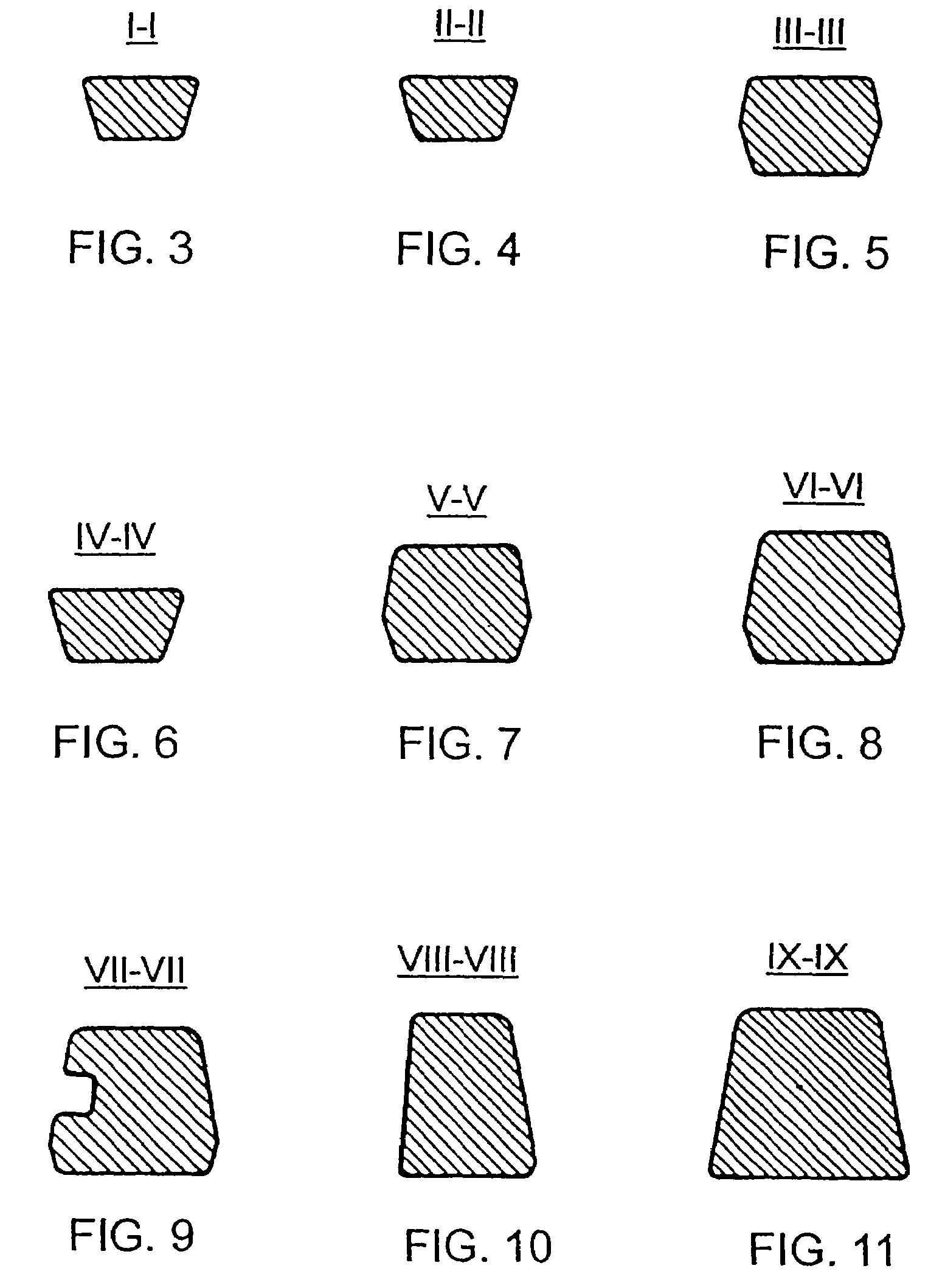
[0022]The tooth coupling projection 2 has a combination of successive regions, which is basically defined, as will be seen in FIGS. 3 to 11, by a structure constituted basically by two inverted dovetails or trapezoids. That is to say, the ...


PUM


Abstract

The device is characterized in that the nose of the tooth-carrier has a general structure in which two end regions thereof, one corresponding to the area of junction of the said nose with the body of the tooth-carrier and the other to the free end of the tooth-carrier, assume in cross-section a dovetail structure, the dovetail at the first end region being inverted compared to the dovetail at the second end region, the cross-section of the end projection of the nose of the tooth-carrier being constant and the upper face of junction of the said projection with the base of the tooth-carrier assuming a curved structure with the convexity directed outwards, the lateral faces of the nose of the tooth-carrier assuming a structure of flat facets, one of them carrying in proximity to the junction with the body of the tooth-carrier a substantially vertical indentation for the coupling of the retaining cotter pin.

Description

RELATED APPLICATIONS[0001]This is a divisional of Application No. 10 / 245,783, filed Sep. 16, 2002, now U.S. Pat. No. 6,836,983 which is a Continuation Application of U.S. Application Ser. No. 09 / 701,235, filed Nov. 22, 2000, now U.S. Pat. No. 6,745,03 which is a National Stage Application filed under §371 of PCT Application No. PCT / ES99 / 00160 filed Jun. 3, 1999; the above noted prior applications are all hereby incorporated by reference.BACKGROUND OF THE INVENTION[0002]The present invention refers to a device for the coupling of excavator teeth which is applicable to the buckets of excavating machines and, in general, to the active working edges of earth-moving machines of similar types.[0003]Machines for civil engineering work which effect the removal of materials such as earth, rocks, etc., generally have active edges on the so-called buckets of the excavators, which are open receptacles of specific shape fixed to the supporting and travelling gear of the machine and which have th...

Claims


Application Information

Patent Timeline
Patent Type & Authority Patents(United States)
IPC IPC(8): E02F9/28
CPCE02F9/2825E02F9/2841E02F9/2833E02F9/28
Inventor PALLAS MORENO, JORGEPUEYO MOLINA, JAVIERSANCHEZ GUISADO, FERMINLOPEZ ALMENDROS, JOSE
Owner METALOGENIA PATENTES
Learn More