
Read and write sample and hold signal generation

a sample and signal technology, applied in the field of optical media, can solve the problems of delay in writing strategy circuit, other problems, undetectable increase of transition noise,

Active Publication Date: 2007-01-23
CSR TECH INC
View PDF13 Cites 6 Cited by
  • Summary
  • Abstract
  • Description
  • Claims
  • Application Information

AI Technical Summary

Benefits of technology

[0019]Accordingly, the present invention includes a method and structure for generating ROPC and RESMP sampling control signals for a sample and hold circuit that ensures sufficient sampling duration and allows for delay compensation.
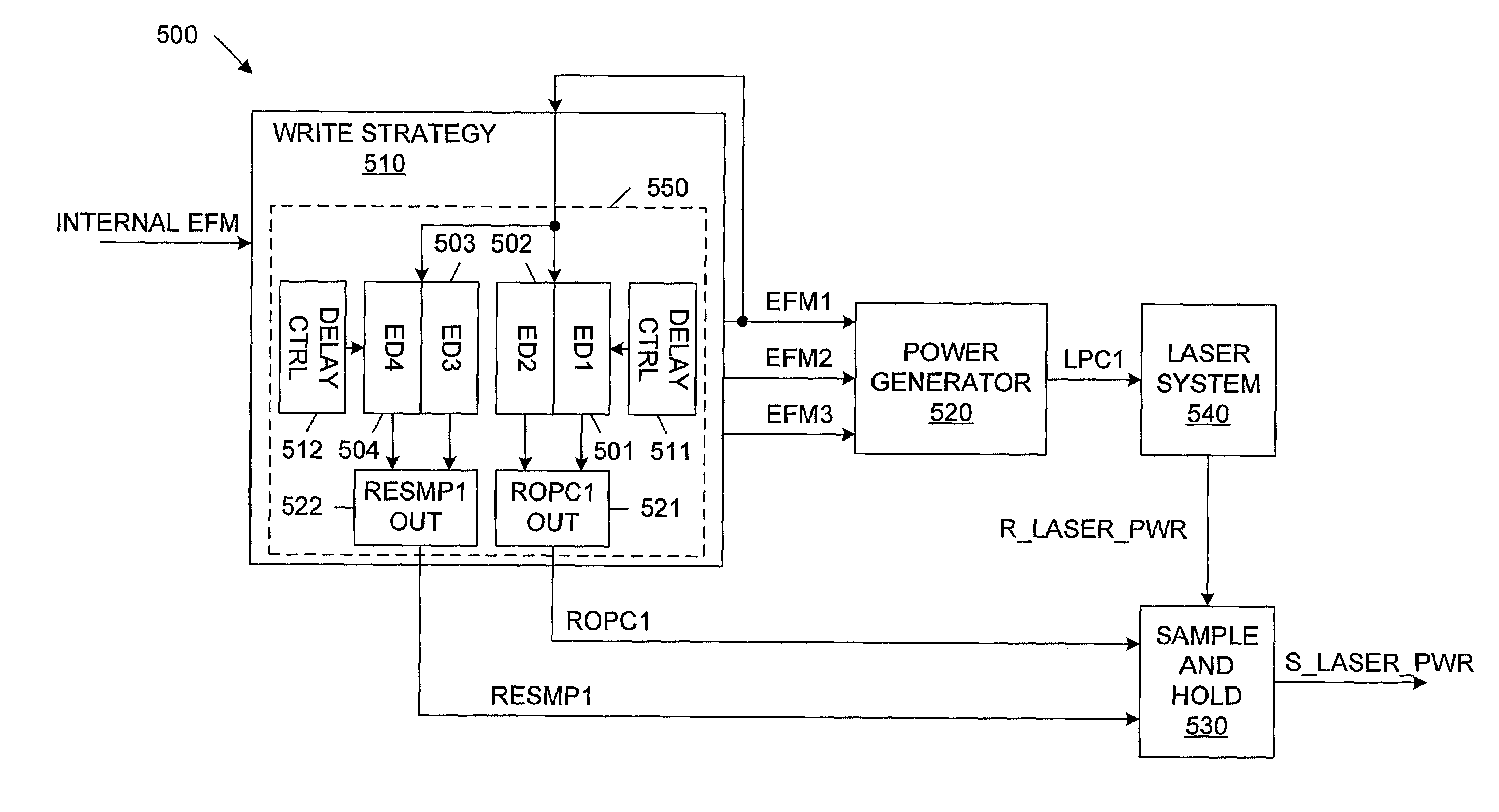
[0020]In one embodiment of the present invention, the ROPC and RESMP sampling control signals are defined from one or more laser power control signals, other than the internal EFM signal, thereby providing more accurate sampling control signals. For example, the ROPC and RESMP sampling control signals can be derived from the EFM1 signal provided at the output terminal of a write strategy circuit, rather than directly from the internal EFM signal provided to the input terminal of the write strategy circuit. In addition, the falling edges of these ROPC and RESMP sampling control signals are enabled to extend beyond the corresponding edges of the internal EFM signal. As a result, the ROPC and RESMP sampling control signals are accurately aligned with the different phases (marks and spaces) of the reflected laser power signal. Consequently, the sampled laser power can be determined more accurately.

Problems solved by technology

Transition noise undesirably increases as operating speed increases.
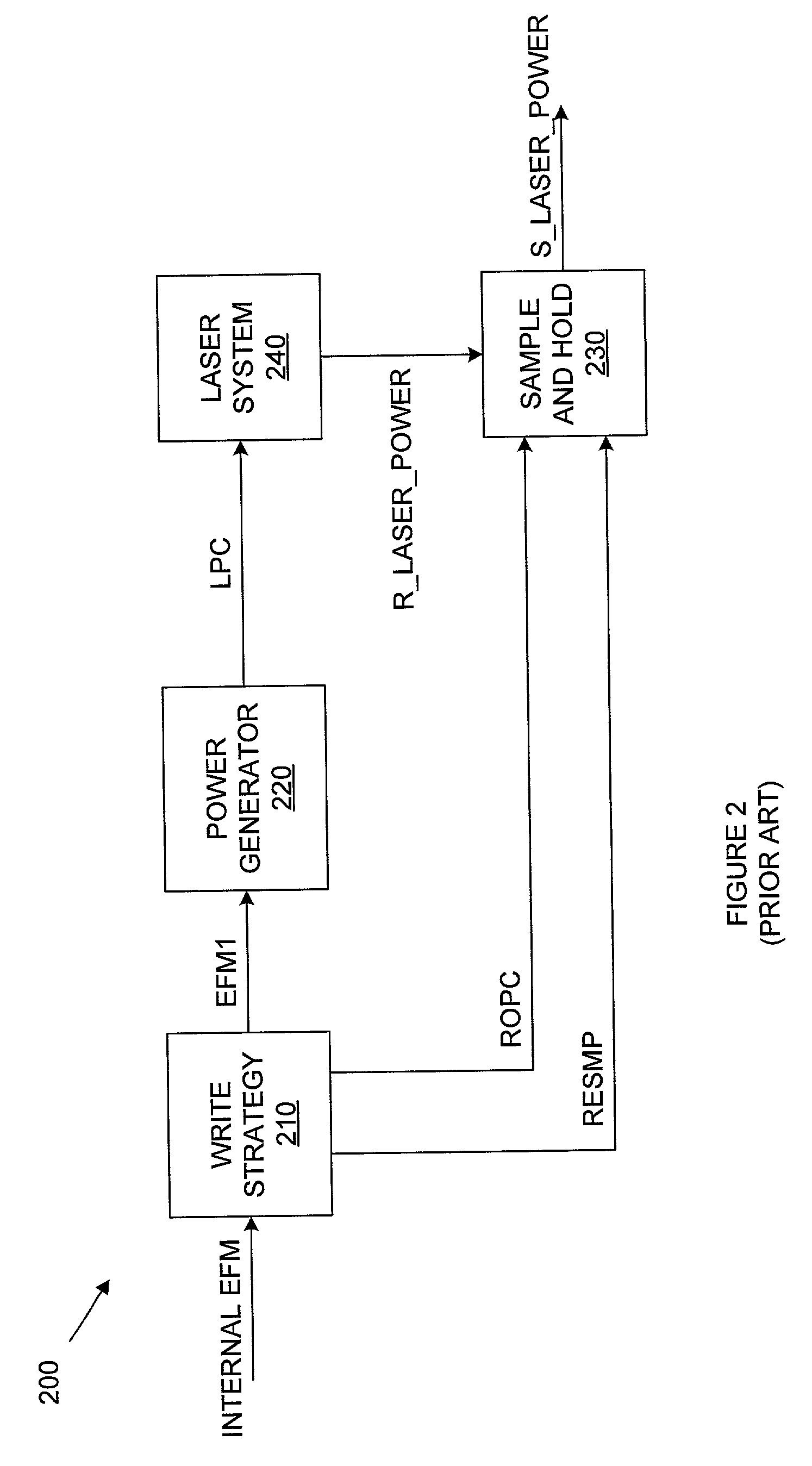
Delay D1 results from delays inherent in the write strategy circuit 210.
However, if the pulse width of the ROPC signal is widened, then other problems will exist.
Thus, pulse FP3 would undesirably cause transition noise and a portion of a space to be sampled.
As a result, pulse FP3 might not be generated in some fixed mode schemes, undesirably resulting in a reduced number of sample points.
That is, as the operating speed is increased, the transition noise of the reflected laser power signal R_LASER_POWER also increases.
As a result, the ROPCA and ROPCB signals undesirably sample the transition noise at the leading edges of the marks of the R_LASER_POWER signal.
Because delay D1 is fixed, there is no way to avoid sampling this transition noise.
Note that the fixed mode presents similar problems when using the RESMP signal to sample the spaces in the R_LASER_POWER signal (e.g., the space resulting from the following space FS).
As a result, the variable mode does not enable shorter marks of the reflected laser power signal R_LASER_POWER to be sampled.
That is, as the operating speed is increased, the transition noise of the reflected laser power signal R_LASER_POWER also increases.
As a result, the ROPC signal undesirably samples the transition noise at the leading edges of the marks of the R_LASER_POWER signal.
Because delay D1 is fixed, there is no way to avoid sampling this transition noise.
Note that the variable mode presents similar problems when using the RESMP signal to sample the spaces in the R_LASER_POWER signal (e.g., the space resulting from the following space FS).

Method used


Image

  • Read and write sample and hold signal generation
  • Read and write sample and hold signal generation
  • Read and write sample and hold signal generation

Examples


Embodiment Construction

[0034]As described below, a write strategy circuit is used to generate ROPC1 and RESMP1 sampling control signals in response to a laser power control signal EFM1, rather than directly in response to an internal EFM signal. The laser power control signal EFM1 is generated in response to the internal EFM signal. Generating the ROPC1 and RESMP1 sampling control signals in response to the EFM1 signal causes these sampling control signals to be more closely aligned with the data to be sampled.

[0035]A user programmable delay circuit is used to generate the ROPC1 and RESMP1 sampling control signals in response to the EFM1 signal. The user programmable delay circuit allows the various edges of the ROPC1 and RESMP1 sampling control signals to be time shifted with respect to corresponding edges of the EFM1 signal. The amount of time shifting is determined by the user by programming the user programmable delay circuit to store user-selected delays. By choosing the user-selected delays in the a...


PUM


Abstract

A system and method for generating sample control signals for a sample and hold circuit used to control access to optical media is provided. The sample control signals are generated with sufficient duration (width) to adequately sample a reflected laser power signal. The sample control signals are defined relative to a laser power command signal generated in response to an internal data stream, rather than directly in response to the internal data stream, thereby allowing for more precise control of the sample control signals. As a result, substantial portions of each pulse of the reflected laser power signal can be sampled, without sampling transition noise that exists when the reflected laser power signal changes states. Generating the sample control signals from a laser power command signal, rather than the input data signal, more accurately time shifts the sampling command to the reflected laser power.

Description

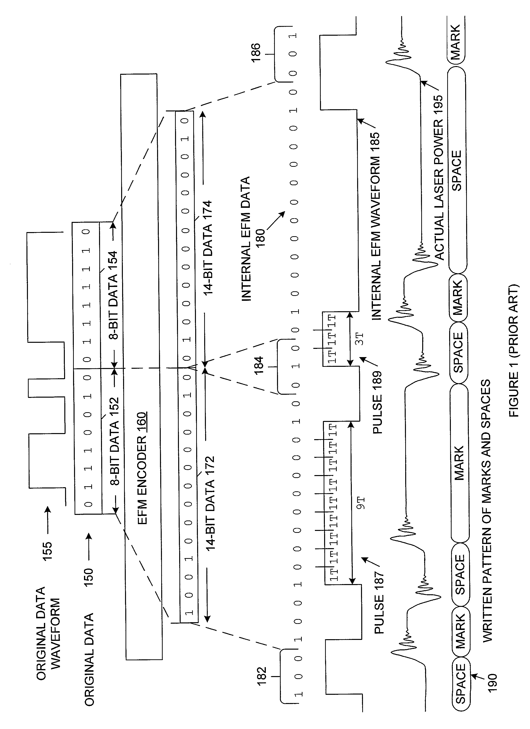
FIELD OF THE INVENTION[0001]The present invention relates to optical media, and more particularly to a system and method for generating sampling control signals for a sample and hold circuit used to control access to the optical media.RELATED ART[0002]Phase changing media and write-once media, such as media used in CD writers, is written to and read from using a multi-pulse laser. A multi-pulse laser uses different laser power levels to burn data onto and read data from the media. For example, when marking a particular type of media, a write operation uses a pre-heat power level to warm up the laser, a peak power level to make an initial mark on the media, a write power level to continue making the mark, and a bias power level to cool down the laser to a non-writing level. While the commands for these power levels are digital, the resulting actual laser power level is analog.[0003]In general, a laser power control signal is generated in response to an internal eight-to-fourteen modu...

Claims


Application Information

Patent Timeline
IPC IPC(8): G11B7/125G11B7/0045G11B7/006G11B20/10G11B20/14
CPCG11B7/00456G11B7/0062G11B7/1263G11B7/1267G11B20/1426G11B20/10009G11B20/1403
Inventor CHIANG, KEVINCHOU, HUNGHUANG, KOUCHIN
Owner CSR TECH INC
Learn More