
Digital camera having controller for reducing occurrences of blur in displayed images

Inactive Publication Date: 2007-01-23
MINOLTA CO LTD
View PDF28 Cites 39 Cited by
  • Summary
  • Abstract
  • Description
  • Claims
  • Application Information

AI Technical Summary

Benefits of technology

[0008]An object of the present invention is to provide a digital camera in which the possibility that a blurred image is displayed on the live view displaying device is reduced.

Problems solved by technology

Moreover, in view of the fact that the power consumption is great when only the live view displaying device is used as the viewfinder, some digital cameras also have optical viewfinders so that switching can be made between the optical viewfinder and the live view displaying device.
However, in conventional digital cameras, sufficient consideration is not given to the relationship between the start timing of driving of the live view displaying device and the timing of focusing.

Method used


Image

  • Digital camera having controller for reducing occurrences of blur in displayed images
  • Digital camera having controller for reducing occurrences of blur in displayed images
  • Digital camera having controller for reducing occurrences of blur in displayed images

Examples


Embodiment Construction

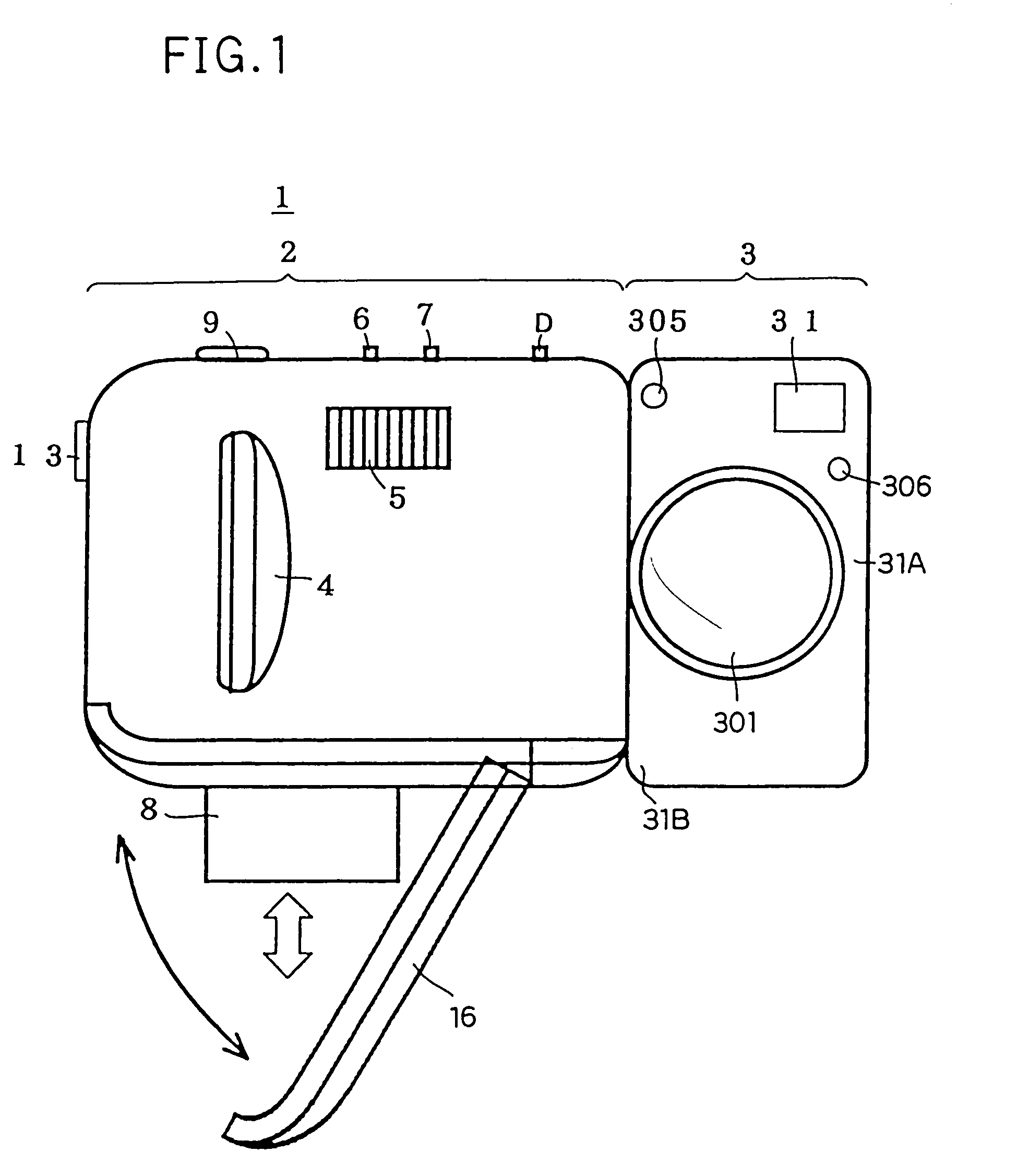
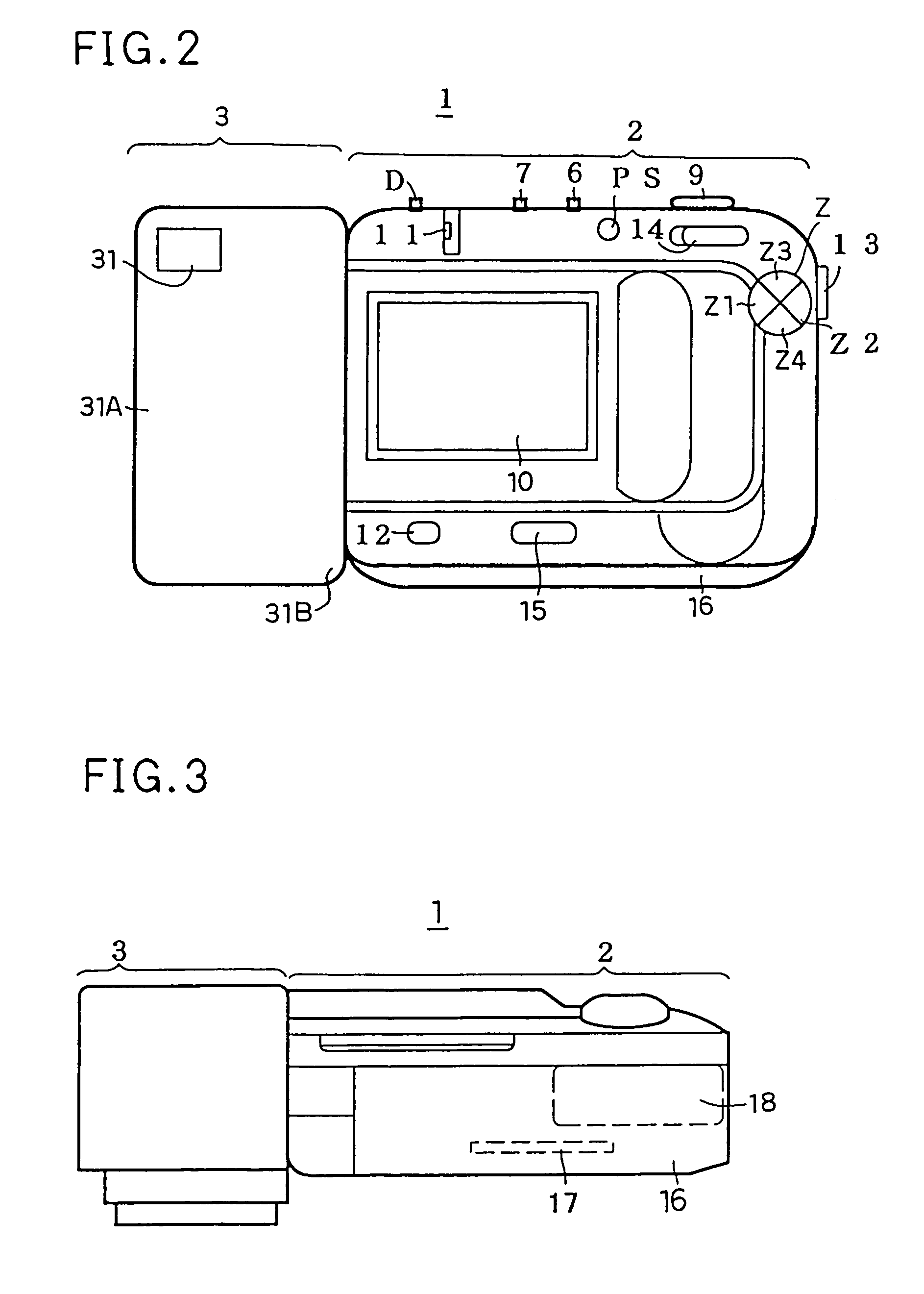
[0022]A digital camera according to the present invention will be described with reference to the drawings. A digital camera 1 according to an embodiment of the present invention has a box-shaped camera body 2 and a rectangular-parallelepiped-shaped image sensing unit 3 as illustrated in FIG. 1 showing a front view of the appearance thereof. First, the camera body 2 will be described. On the front surface of the camera body 2, a grip 4 is disposed in an appropriate position in a left end part, and a built-in flash 5 is disposed in an appropriate upper position in a right end part. On the top surface of the camera body 2, switches 6 and 7 for advancing frames when recorded images are reproduced are disposed substantially in the center.

[0023]The switch 6 is for advancing frames of recorded images in a direction that increases the frame number that is, a direction of the order of shooting (hereinafter, the switch 6 will be referred to as “UP switch”). The switch 7 is for advancing fram...


PUM


Abstract

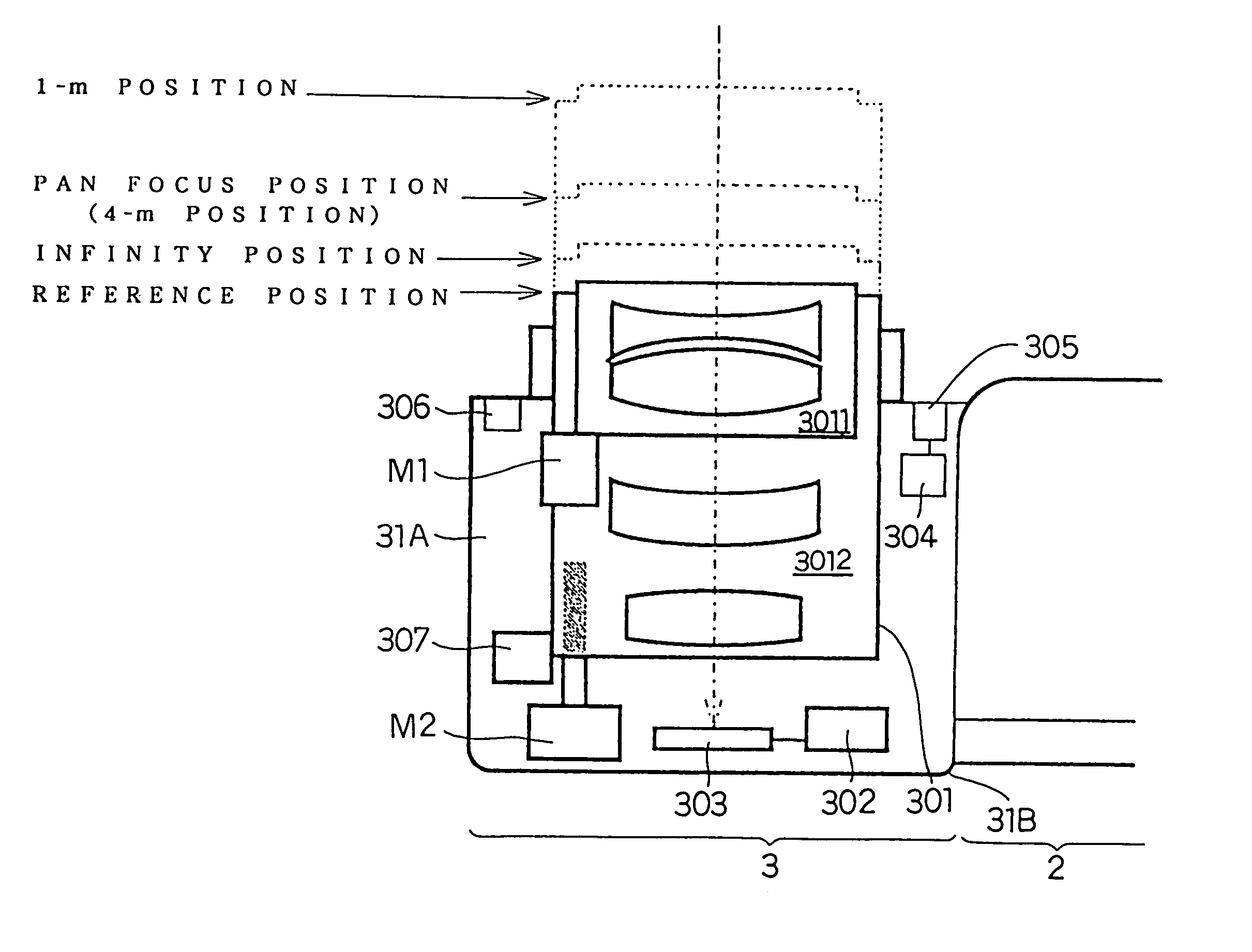
A digital camera comprises a camera body and an image sensing unit. The image sensing unit is provided with a taking lens and an image sensing device for taking images and with an optical viewfinder. The camera body is provided with a controller for controlling the camera, signal processing circuits for processing signals from the image sensing device, a display device for displaying images taken and an interface for recording images taken onto a memory card. The display device serves as a viewfinder. In taking a image, the controller performs an AF control of the taking lens. When power supply to the camera is started, and when the display device is activated, the controller sets the taking lens at a predetermined focus position where in-focus condition is obtained for distant to close-range views, so that blurred images are not displayed on the display device.

Description

[0001]This application is based on application No. H10-215389 filed in Japan on Jul. 30, 1998, the entire content of which is hereby incorporated by reference.BACKGROUND OF THE INVENTION[0002]1. Field of the Invention[0003]The present invention relates to a digital camera that converts a subject image into electric signals and records the electric signals.[0004]2. Description of the Prior Art[0005]In recent years, with the development of the semiconductor technology such as image sensing devices, CPUs and memories, so-called digital cameras have become widespread in which a subject image is converted into image signals by use of an image sensing device such as a CCD instead of film, and after processed by a CPU, the image signals are recorded onto recording device.[0006]Digital cameras are provided with live view displaying device for displaying an image currently taken by the image sensing device through the taking lens. The live view displaying device can be used as the viewfinder...

Claims


Application Information

Patent Timeline
IPC IPC(8): H04N5/232G03B13/00G03B13/32G03B3/00H04N5/222G03B13/02G03B13/18G03B19/02
CPCG03B3/00G03B13/18G03B13/32H04N5/23212H04N5/23293G03B19/02H04N2101/00H04N23/67H04N23/63
Inventor YUKAWA, KAZUHIKONIIKAWA, MASAHITO
Owner MINOLTA CO LTD
Learn More