
Gate driver and electroluminescence display device including the same

a technology of electroluminescent display and gate driver, which is applied in the direction of instruments, static indicating devices, etc., can solve the problems of uneven luminance and image quality, and achieve the effects of reducing the size of the connected transistor, and improving the reliability of the connected transistor

Active Publication Date: 2019-05-23
LG DISPLAY CO LTD
View PDF3 Cites 1 Cited by
  • Summary
  • Abstract
  • Description
  • Claims
  • Application Information

AI Technical Summary

Benefits of technology

The patent describes a new way to improve the operation of a device called a gate driver, which is used to control the timing of data transmission in a display. The new approach involves using a special voltage to activate a specific component in the device, which helps to make the device more reliable and reduces its size. This can result in a smaller bezel for the display, making it more visually appealing. The research is still ongoing to determine the best way to improve the reliability of the gate driver, but the new approach is a promising start.

Problems solved by technology

If the voltage is not accurately applied to the sub-pixels, there can be image quality issues such as uneven luminance in the vertical direction and cross-talk on the display panel.

Method used


Image

  • Gate driver and electroluminescence display device including the same
  • Gate driver and electroluminescence display device including the same
  • Gate driver and electroluminescence display device including the same

Examples


Embodiment Construction

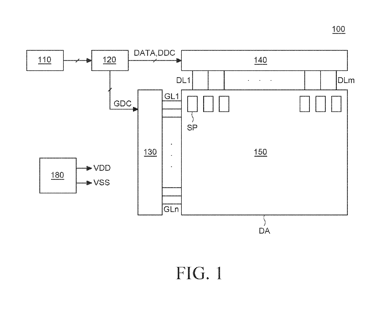
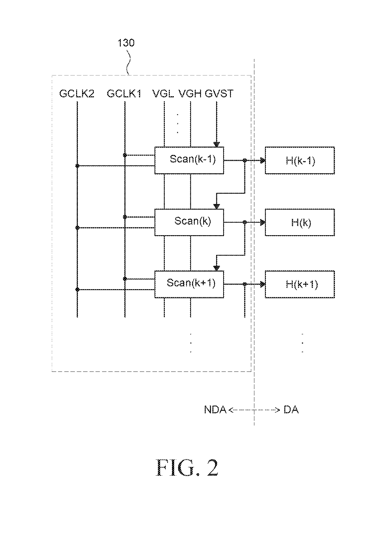
[0030]Advantages and features of the present disclosure and methods to achieve them will become apparent from the descriptions of embodiments hereinbelow with reference to the accompanying drawings. However, the present disclosure is not limited to embodiments disclosed herein but can be implemented in various different ways. The embodiments are provided for making the disclosure of the present disclosure thorough and for fully conveying the scope of the present disclosure to those skilled in the art. It is to be noted that the scope of the present disclosure is defined only by the claims.

[0031]The figures, dimensions, ratios, angles, the numbers of elements given in the drawings are merely illustrative and are not limiting. Like reference numerals denote like elements throughout the descriptions. And, in describing the present disclosure, descriptions on well-known technologies can be omitted in order not to unnecessarily obscure the gist of the present disclosure. It is to be noti...


PUM


Abstract

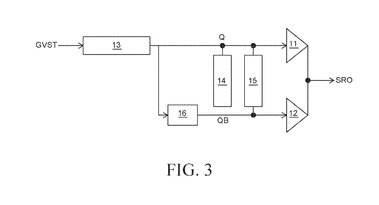
An electroluminescent display device includes sub-pixels connected to gate lines, and a gate driver configured to supply a scan signal to at least one of the gate lines, and including stages. One of the stages includes a QB-node regulation unit configured to charge a QB-node and a QP-node to turn-on voltage by using a first gate clock signal and a second gate clock signal, and a pull-down unit configured to output a turn-off voltage in response to a voltage of the QP-node. The QB-node regulation unit includes a QP-node control part configured to invert a phase of a voltage of a Q1-node and apply the voltage of the inverted phase to the QP-node, and a QB-node control part configured to bootstrap the QP-node. Accordingly, by employing the gate driver including the QB-node regulation unit that provides a stable voltage to the QB-node and the QP-node, the reliability of the gate driver can be improved, and the bezel of the electroluminescence display device can be reduced.

Description

CROSS-REFERENCE TO RELATED APPLICATIONS[0001]This application claims the priority of Korean Patent Application No. 10-2017-0155741 filed on Nov. 21, 2017, in the Korean Intellectual Property Office, the disclosure of which is incorporated herein by reference.BACKGROUNDTechnical Field[0002]The present disclosure relates to a gate driver with improved performance and an electroluminescent display device including the same.Description of the Related Art[0003]As the information technology evolves, the market for display devices as media providing users with information is growing. Accordingly, various types of display devices such as an electroluminescence display device, a liquid-crystal display device and a quantum-dot display device are increasingly used.[0004]A display device includes a display panel including a plurality of sub-pixels, a driver unit for driving the display panel, a power supply unit for supplying power to the display panel, etc. The driver unit includes a gate driv...

Claims


Application Information

Patent Timeline
Patent Type & Authority Applications(United States)
IPC IPC(8): G09G3/30
CPCG09G2320/0233G09G2320/0209G09G2310/0267G09G3/30G09G3/3266G09G2300/0408G09G2310/0286G09G2310/08G09G2230/00
Inventor KONG, CHUNGSIKSHIN, MIHEEKANG, GYUTAE
Owner LG DISPLAY CO LTD
Learn More