Automatic path planning system and method

a path selection and automatic technology, applied in the field of three-dimensional medical imaging data sets, can solve the problems of tissue damage, dangerous and painful use of physical endoscopes, and achieve the effects of reducing granularity, reducing granularity, and increasing the speed of algorithm

Inactive Publication Date: 2007-01-23
ALGOTEC SYST
View PDF4 Cites 172 Cited by
  • Summary
  • Abstract
  • Description
  • Claims
  • Application Information

AI Technical Summary

Benefits of technology

[0012]Another object of some preferred embodiments of the invention is to provide a method of planning a path for virtual endoscopy, in which the path is not limited to remaining in substantially the middle of a cavity through which the path passes. In a preferred embodiment of the invention, the path does not pass too close to the boundaries of—and / or obstacles in—the cavity.
[0013]Another object of some embodiments of the present invention is to provide a method of planning a path which is not adversely affected by small errors in the acquisition of the data, especially not affected by small holes in the boundary of the cavity.
[0015]Another object of some embodiments of the present invention is to provide a method of path planning which directly uses voxel data, thereby avoiding the necessity to generate a surface representation and possibly add errors.
[0029]Additionally or alternatively, the penalty value associated with a point may depend on the path chosen or a portion of the path, for example, the amount of twist in the path. In a preferred embodiment of the invention, a relatively short duration is desired for the travel along the path. Thus, points which reduce the duration are preferred over points which increase the duration. In one example, the velocity of motion allowed through a certain point may be inversely dependent on the amount of bending in the path. Thus, points which increase the bend, increase the duration and have a lower desirability even though they shorten the path.
[0042]In a preferred embodiment of the invention, the granularity does not affect all the steps of the algorithm. In one preferred embodiment of the invention, the granulation is embodied by determining the step size and / or the minimal radius used in the erosion and / or skeletonization step. Alternatively or additionally, the local granularity is made inversely related to the penalty function, in the path finding step. Preferably, in voxels where there are large changes in the penalty function and / or where the penalty function is high, the granularity is finer. Preferably, the granularity is anisotropic.
[0043]In a preferred embodiment of the invention, the amount and / or type of smoothing is dependent on the local width of passages. Path portions which pass through narrow passages are preferably not smoothed at all, to reduce the chance of the path entering a cavity boundary and / or passing to close to a boundary.

Problems solved by technology

Using physical endoscopes raises several problems.
First, even though the endoscopic procedure is minimally invasive, it still involves inserting a surgical instrument into the body, which is both dangerous and painful.
In addition, forcing a passage from the outside of the body and into the elongate cavity may cause tissue damage.
Another problem is that the field of view and maneuverability of the endoscope are limited.
Since the precise position of the endoscope and the point of view of the endoscope are difficult to determine, navigating in the body using an endoscope is difficult.
Manual planning of the path is a long process and while it might sometimes be desirable that the attending physician perform this task, he will seldom have the time to do so.
However, such a path may pass very close to the obstacles.
One limitation of medial axis following is that the medial axis is not smooth, but is affected by the morphology of the passage, even if the passage is very wide.
Thus, a bump in the passage wall causes a bump in the path.

Method used


Image

  • Automatic path planning system and method
  • Automatic path planning system and method
  • Automatic path planning system and method

Examples


Embodiment Construction

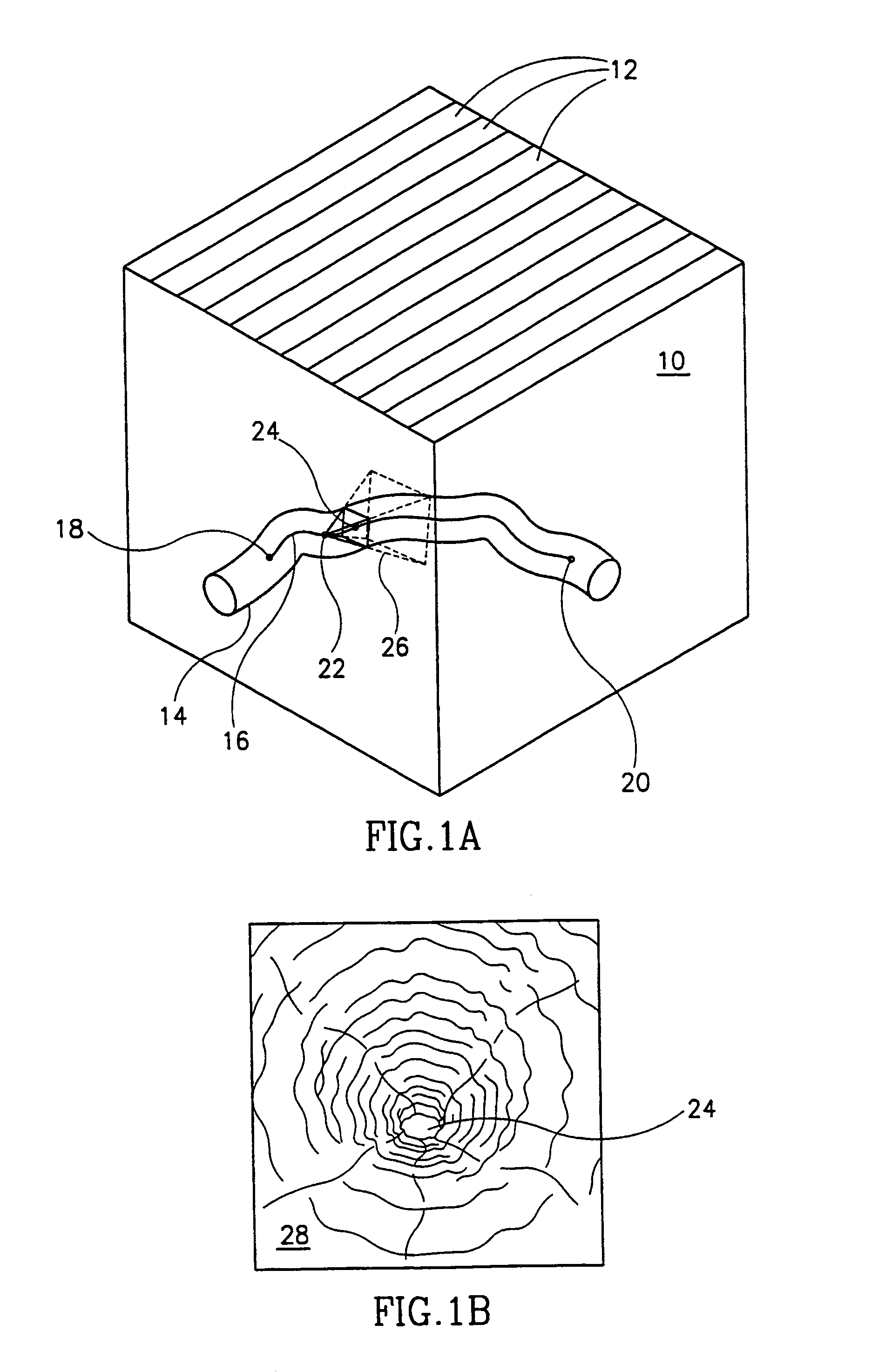
[0088]FIG. 1A is a schematic illustration of a three-dimensional data set 10, including a cavity 14 and a path 16 through the cavity. Data set 10 usually comprises a plurality of image slices 12, however, in many cases, it is desirable to view portions of the data set, as seen from a view origin point 22 along path 16. This view is defined by a view origin point 22 staring at a view aiming point 24 through a viewport 26. In some cases, it may be more convenient to describe the viewport as being centered around a line of sight between the view origin point and the aiming point. It should be appreciated that the view may be clipped, so that voxels that are very close to the view origin point are not viewed. In an orthogonal projection, the view origin point can be in one of many places along the line of sight, however a fixed location is usually supplied. FIG. 1B is a schematic illustration of a view 28 seen through viewport 26.

[0089]A system, in accordance with some preferred embodim...


PUM


Abstract

A method of path planning, comprising providing a dataset representing a cavity and a boundary; providing a plurality of points in said dataset, including at least a starting point and an ending point; and automatically determining a path between the starting point and the ending point, responsive to a penalty associated with passing through points in the cavity. Preferably, the penalty value associated with a point depends on a distance between the point and the boundary.

Description

RELATED APPLICATION[0001]This application is a US national filing of PCT Application PCT / IL98 / 00087, filed Feb. 23, 1998.FIELD OF THE INVENTION[0002]The present invention relates to the display of three-dimensional medical imaging data sets, and in particular to automatic path selection for virtual endoscopy.BACKGROUND OF THE INVENTION[0003]In many medical situations it is necessary to obtain views of elongate cavities within the body, from within the cavities. Some common examples include blood vessels, intestines and the bronchi. An endoscope (and other, similar devices, collectively referred to herein as endoscopes) is a device which can be inserted into such a cavity and through which a small portion of the cavity can be viewed in real-time and with high-resolution.[0004]Using physical endoscopes raises several problems. First, even though the endoscopic procedure is minimally invasive, it still involves inserting a surgical instrument into the body, which is both dangerous and ...

Claims


Application Information

Patent Timeline
IPC IPC(8): G06T15/00A61B1/00A61B6/00A61M25/00G06Q50/00G06T5/30
CPCG06T7/0091G06T7/0085A61B6/5205A61B6/506A61B6/466G06T2207/30172G06T2207/30101G06T7/13G06T7/155
Inventor SHIBOLET, OMER
Owner ALGOTEC SYST
Why Eureka
Try Eureka