
Knee-ankle-foot positioning kit

a positioning kit and knee technology, applied in the field of knee-ankle-foot positioning kits, can solve the problems of affecting the movement of the patient's legs, affecting the patient's health, and affecting the patient's ability to prevent undesired movement, so as to restrict the movement of the affected hips

Active Publication Date: 2007-01-23
BREG
View PDF37 Cites 51 Cited by
  • Summary
  • Abstract
  • Description
  • Claims
  • Application Information

AI Technical Summary

Benefits of technology

Effectively restricts harmful hip movements while allowing necessary mobility, promoting healing and protecting the feet from injury during traction, thereby reducing the risk of dislocation and re-injury, and facilitating the healing process.

Problems solved by technology

There are a number of issues that result from conducting hip surgery.
As a result of being secured to the traction plates and the traction that is being applied, the feet may be bruised and / or otherwise injured.
At the same time, it is also undesirable to restrict the movement of the patient's legs more than necessary, in order to help heal and strengthen the muscles surrounding the affected hip joint.
It is often difficult for the patient to prevent undesired movement of the leg, especially while sleeping.
This also creates opportunities for the leg to move in an undesirable manner.
If the leg is allowed to move in undesired directions, such as rotating, abducting, or adducting, there is a significant chance the hip joint will be dislocated or further injured, thereby prolonging the healing process or even necessitating further treatment or additional surgery.
However, this generally does not prevent the rotation of the hip, since only the leg is secured to the pillow with straps, while the foot remains free and allows the leg to rotate.
This prevents the patient from exercising the leg in any way without completely removing the wedged pillow, thereby leaving the leg without any support whatsoever.

Method used


Image

  • Knee-ankle-foot positioning kit
  • Knee-ankle-foot positioning kit
  • Knee-ankle-foot positioning kit

Examples


Embodiment Construction

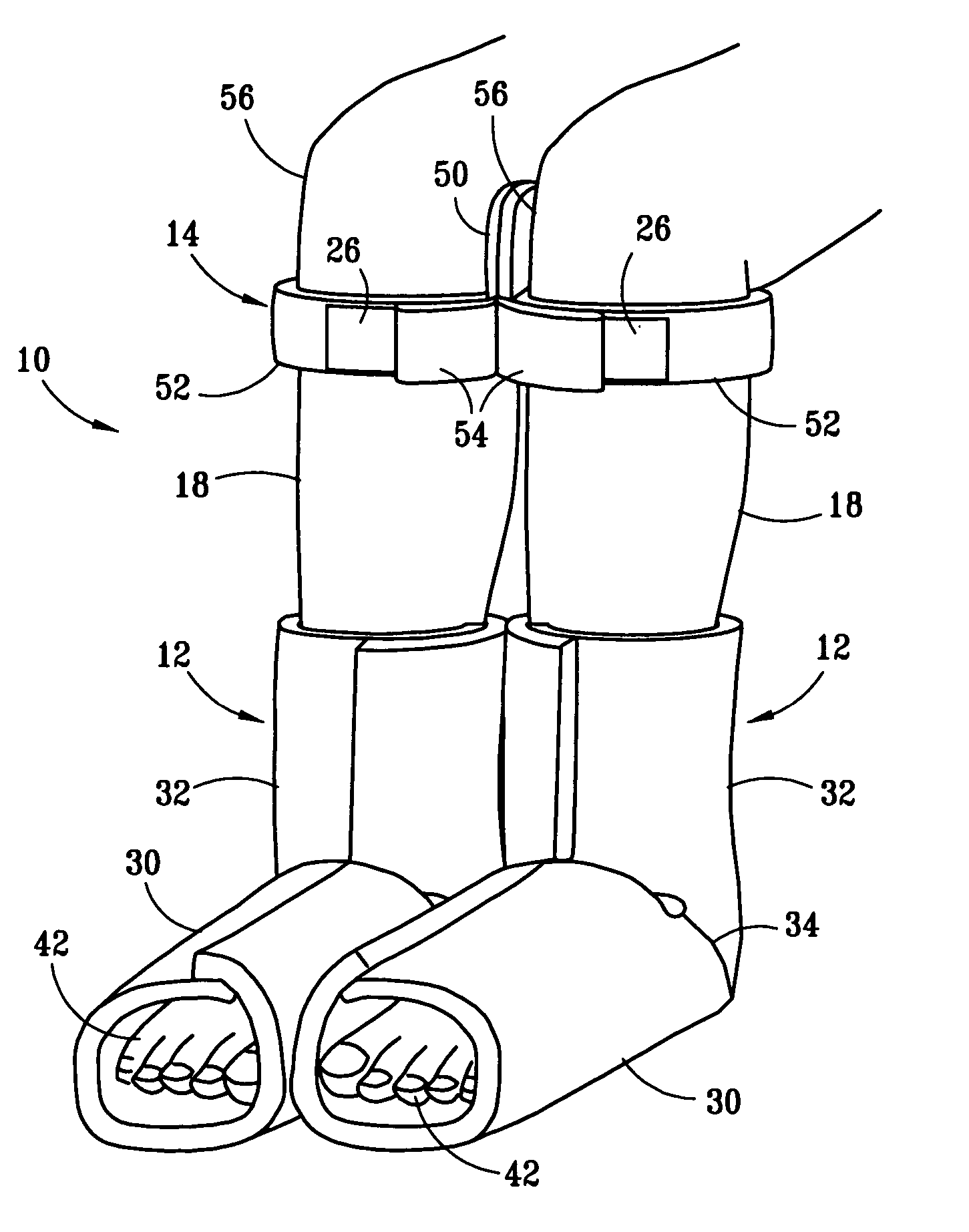
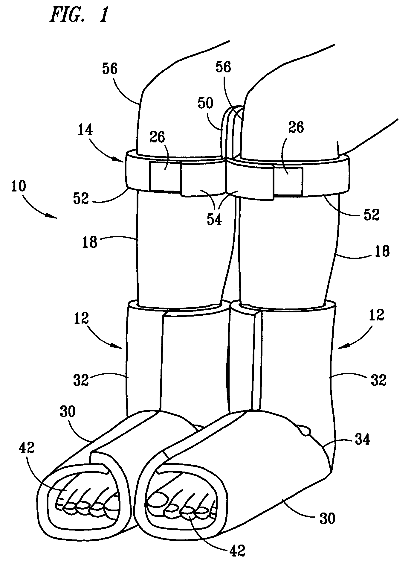
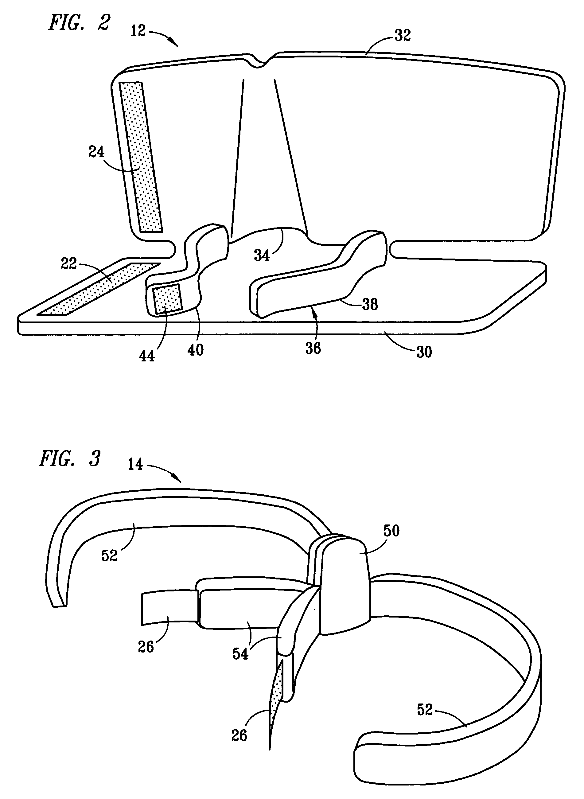
[0017]In a preferred embodiment, positioning system 10 is generally composed of boots 12 and knee strap 14. Boots 12 and knee strap 14 are preferably composed of thick breathable foam material in order to provide comfort while securely holding legs 18 in the desired position. The surface of boots 12 is composed of many loops that can be used as the loop portion of a hook and loop fastener, such as VELCRO® brand fasteners. These loops can be formed as the integral outer surface of the foam material of boots 12 or it can be a separate material that is secured to the outer surface of the foam in any manner known to those of skill in the art, such as heat fusion or through the use of adhesives. Closure strips 22, 24, and 26 are made up of a plurality of hook segments on one side that make up the other half of a hook and loop fastener system with the loops on the surface of boots 12. Double-sided hook strips 28 are similar to closure strips 22, 24, and 26 except that double-sided hook st...


PUM


Abstract

A positioning system used to limit movement of the leg, such as when required after hip surgery. In at least one embodiment, a boot, which extends around the foot and lower leg, is secured around each foot. As such, the boots can be used to cushion the feet while applying traction to the leg during surgery. After surgery, the boots are secured together in a side-by-side relationship. In addition, a leg strap is preferably used in conjunction with the boots to help hold the legs together. The leg strap preferably has a cushion that is positioned between the knees with a strap that is secured around each leg. Consequently, the positioning kit restricts certain motion of the affected hip while not restricting movement of the hips and knee and ankle joints unnecessarily.

Description

BACKGROUND OF THE INVENTION[0001]1. Field of the Invention[0002]This invention relates generally to a leg positioning kit and, more particularly, to a leg positioning kit capable of restricting certain movement of the hip following surgery.[0003]2. Description of Related Art[0004]There are a number of issues that result from conducting hip surgery. First, during surgery it is generally necessary to provide traction on the leg in order to hold the bones in the desired position. This traction is often applied by securing the feet to traction plates on a traction table and pulling them away from the hip. As a result of being secured to the traction plates and the traction that is being applied, the feet may be bruised and / or otherwise injured.[0005]Second, during surgery a number of muscles, tendons, and other connective tissue that help maintain the hip in its socket are pulled away or cut in order to provide the surgeon access to the hip joint. After surgery it is important to restri...

Claims


Application Information

Patent Timeline
Patent Type & Authority Patents(United States)
IPC IPC(8): A61F5/00A61F5/01
CPCA61F5/0116
Inventor BLEDSOE, GARY R.
Owner BREG
Learn More