
Bipolar battery

a battery and bipolar technology, applied in the field of bipolar batteries, can solve the problems of short circuit, called liquid junction, between single cells, and achieve the effect of preventing the liquid junction between single cells

Active Publication Date: 2007-01-16
NISSAN MOTOR CO LTD
View PDF9 Cites 61 Cited by
  • Summary
  • Abstract
  • Description
  • Claims
  • Application Information

AI Technical Summary

Benefits of technology

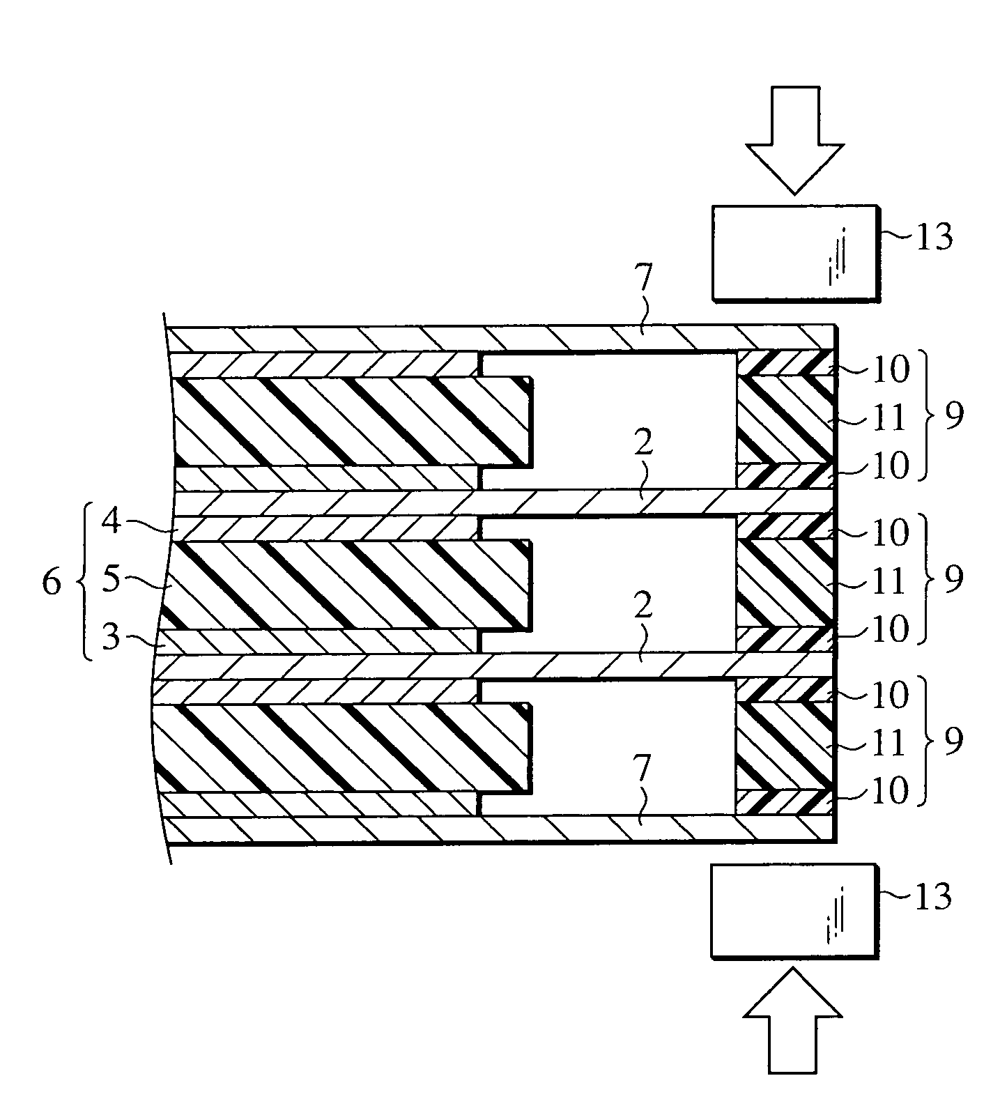
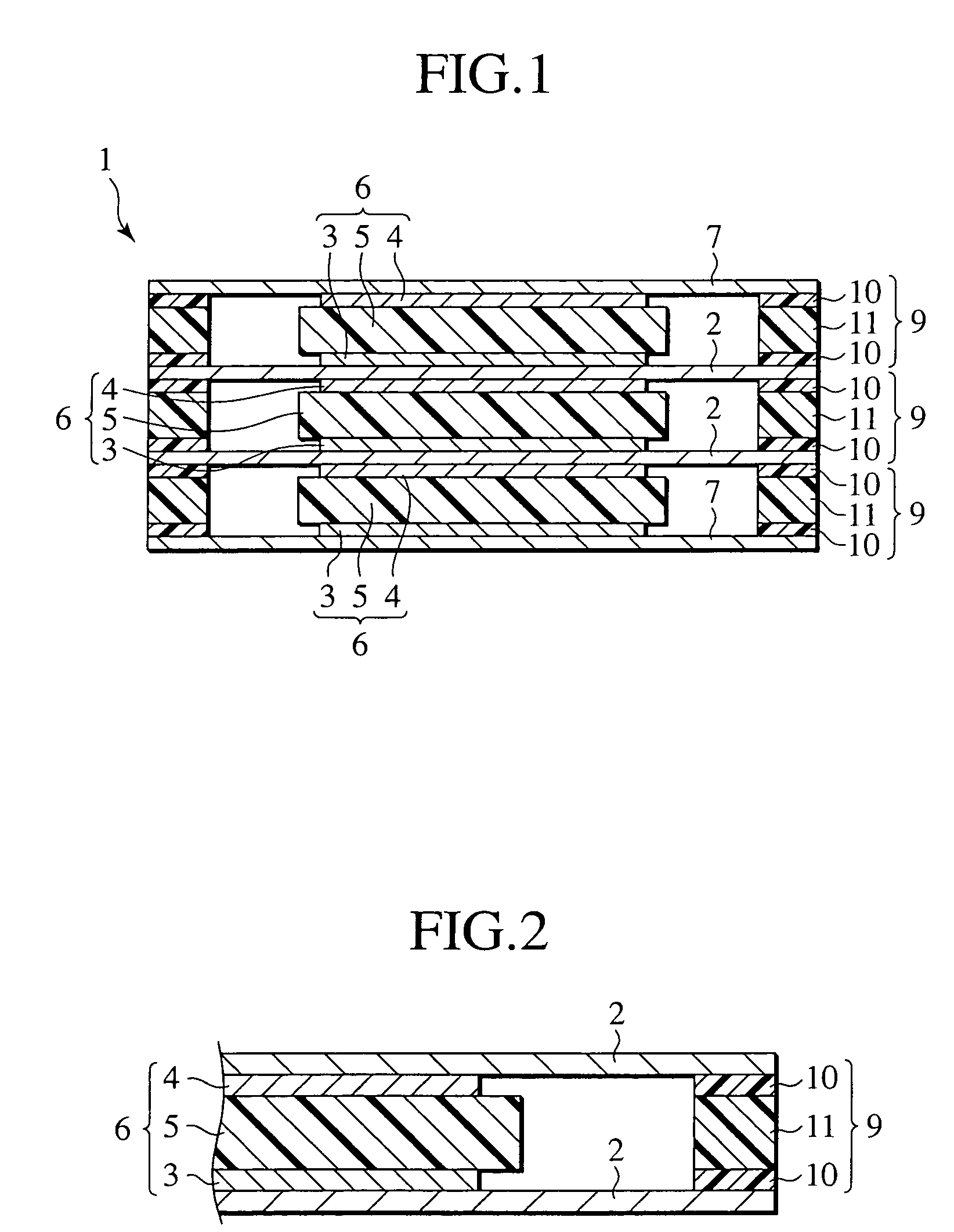
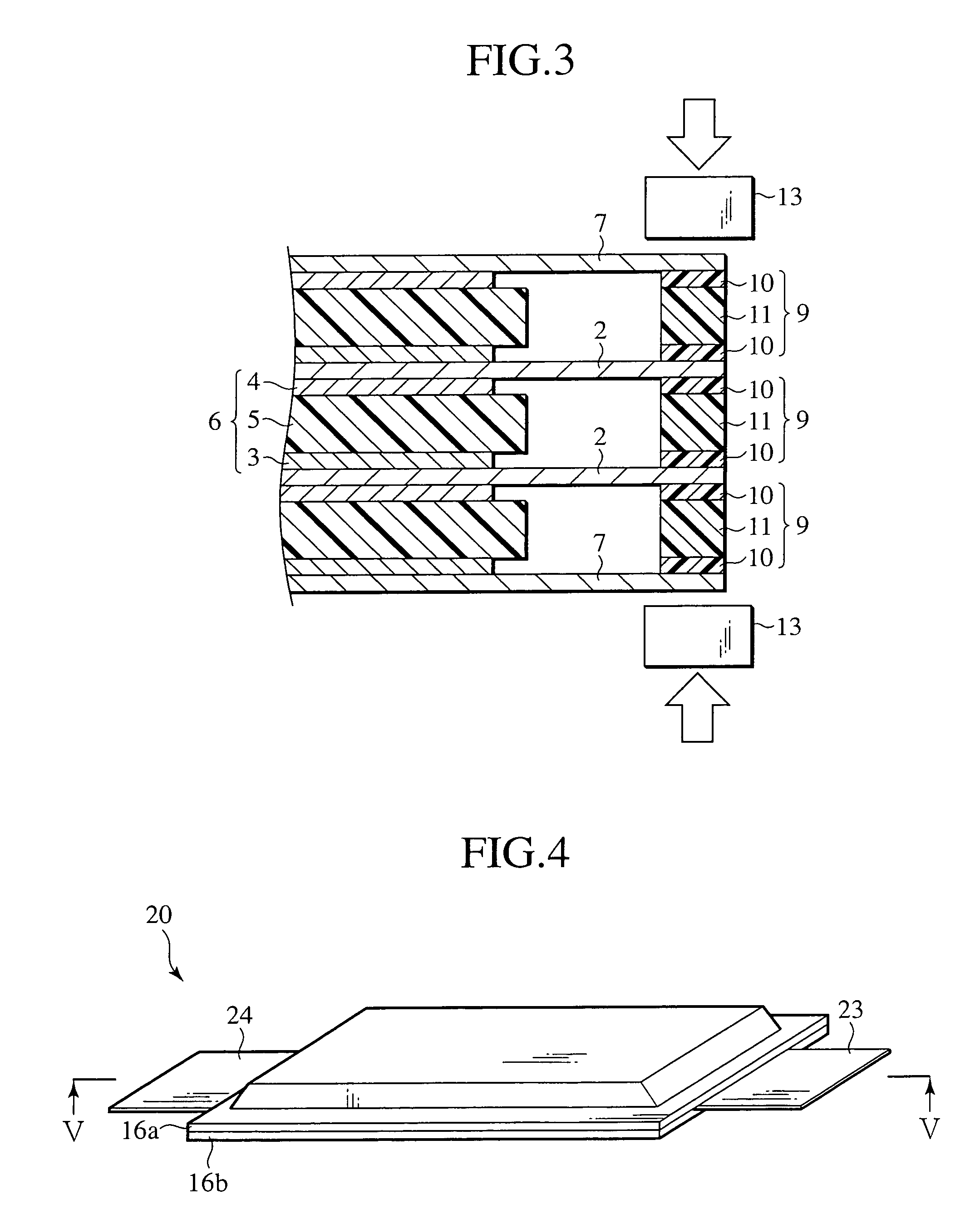
[0007]The present invention was made in consideration of the above-described problems. It is an object of the present invention to provide a bipolar battery in which the liquid junction between the single cells is prevented even when stacking the plurality of single cells using the polymer gel electrolyte to construct the bipolar battery.

Problems solved by technology

However, when constructing a single cell using the polymer gel electrolyte and stacking a plurality of the single cells to make a bipolar battery, there has been a problem that the electrolyte oozes between each of the single cells and contacts with the electrolyte of another single cell, thus causing a short circuit, called a liquid junction, between the single cells.

Method used


Image

  • Bipolar battery
  • Bipolar battery
  • Bipolar battery

Examples


second embodiment

[0089]A second embodiment of the present invention is an assembled battery in which the plurality of the bipolar batteries 20 of the foregoing first embodiment is connected to each other.

[0090]As shown in FIGS. 8 and 9, in this assembled battery 50, the plurality of bipolar batteries 20 of the foregoing first embodiment which is connected in series is further connected in parallel. Between the bipolar batteries 20, the positive electrode leads 23 and the negative electrode leads 24 of each of the batteries are connected by conductive members 53. The plurality of bipolar batteries which is electrically connected is connected to terminals 51 and 52 provided on one side surface of the assembled battery 50.

[0091]In this assembled battery 50, the terminals of the batteries 20 and the conductive members 53 can be connected using a method such as ultrasonic welding, heat welding, laser welding, rivet, crimping and electron beam. By using such a connecting method, it is possible to manufact...

third embodiment

[0094]A third embodiment is an assembled battery module in which the plurality of assembled batteries of the aforementioned second embodiment are connected to each other.

[0095]As shown in FIG. 10, the assembled battery module 60 is formed into a module in a way that the plurality of assembled batteries 50 of the foregoing second embodiment are stacked, and the terminals 51 and 52 of each of the assembled batteries 50 are connected by conductive members 61 and 62.

[0096]The modularization of the assembled batteries 50 in this way facilitates battery control and forms an optimal assembled battery module to be mounted on a vehicle such as an electric vehicle and a hybrid vehicle. The assembled battery module 60 has a long-term reliability since the foregoing assembled batteries are used therefor.

[0097](Fourth Embodiment)

[0098]A fourth embodiment is a vehicle which mounts the assembled battery module according to the aforementioned third embodiment and uses the assembled battery module a...


PUM

PropertyMeasurementUnit
Temperatureaaaaaaaaaa
Melting pointaaaaaaaaaa

Abstract

A bipolar battery comprises a bipolar electrode in which a positive electrode is provided on one surface of a collector and a negative electrode is provided on the other surface of the collector, a gel electrolyte sandwiched between the positive electrode and the negative electrode, and a sealing layer which is provided between the collectors and surrounds a periphery of a single cell including the positive electrode, the negative electrode, and the gel electrolyte.

Description

BACKGROUND OF THE INVENTION[0001]1. Field of the Invention[0002]The present invention relates to a bipolar battery.[0003]2. Description of the Related Art[0004]Lithium ion secondary batteries include those using a solid electrolyte, a liquid electrolyte, and a polymer gel electrolyte, respectively, as electrolytes to be encapsulated therein.[0005]The lithium ion secondary battery using the solid electrolyte is that using a solid polymer electrolyte, such as polyethylene oxide, as the only electrolyte thereof. On the other hand, for the liquid electrolyte, only an electrolysis solution is used. The polymer gel electrolyte is considered to be an intermediate of a solid electrolyte and a liquid electrolyte. The polymer gel electrolyte includes one in which an electrolysis solution is held among chains of polymer such as polyvinylidene fluoride (PVDF) which has no lithium ion conductivity in itself (refer to Japanese Patent Application Laid-Open No. H11-204136).SUMMARY OF THE INVENTION[...

Claims


Application Information

Patent Timeline
IPC IPC(8): H01M2/08H01M6/48H01M6/22H01M6/46H01M10/05H01M4/64H01M10/04H01M10/0525H01M10/0565H01M10/058H01M10/0585H01M50/186H01M50/193H01M50/197
CPCH01M2/08H01M4/48H01M6/48H01M10/0585H01M10/0418H01M4/485H01M4/5825H01M4/587Y10T29/4911H01M10/0525H01M10/0565H01M2300/0082Y02T10/7011Y02E60/122Y02E60/10Y02P70/50H01M50/186H01M50/193H01M50/197
Inventor HOSAKA, KENJIFUKUZAWA, TATSUHIRONEMOTO, KOUICHI
Owner NISSAN MOTOR CO LTD
Learn More