Bonding of a plastic fixture to a glass container

a technology for plastic fixtures and glass containers, applied in the direction of container/bottle construction, rigid containers, domestic vessels, etc., can solve the problems of glass breakage, poor bonding properties, safety risks, etc., and achieve the effect of less cross-section

Inactive Publication Date: 2007-01-16
SCHOTT AG
View PDF6 Cites 1 Cited by
  • Summary
  • Abstract
  • Description
  • Claims
  • Application Information

AI Technical Summary

Benefits of technology

[0004]The bond of a plastic fixture on a glass container in accordance with one form of the invention is characterized by a positive bond between the plastic fixture and a slotted wraparound element which encloses the exterior of the glass container in the opening area in an area of lesser cross-section than at the opening. By opening area, that area is understood in connection with the opening, which is constructed tapered across from the remaining glass container with regard to the cross-sectional area. The wraparound element is dimensioned with regard to its geometry and dimensions in such a way that its inner circumference has greater dimensions than the outer circumference in the area of lower cross-section of the opening area, but lesser dimensions than the following area of the opening area up to the opening. Arranged at the outer circumference of the wraparound element, there is, proceeding in a circumferential direction, preferably a rotary recess or number of recesses proceeding in a circumferential direction at specific intervals to each other. According to the invention these recesses interact in a form-locking manner with complementary constructed projections at the inner circumference of the plastic fixture, in particular in the form of a snap connection. For this purpose the plastic fixture has two walls which enclose both sides of the wall of the glass container in fitting position in the opening area in circumferential direction , which can also be referred to as lips and are an integral component of the plastic fixture. These lips are arranged at the inside circumference and constructed directed toward the glass container. The first inner wall is arranged in fitting position in the opening, the second outer wall encloses the wall of the glass container in the opening area from the outside. The attachment of the plastic fixture thus occurs indirectly, i.e. not directly at the walls of the glass container, but rather by means of the wraparound element, which in turn abuts the outer wall of the glass container at least with a part of its interior surface. The projection or projections at the inner circumference of the plastic fixture are arranged at the interior surface pointing to the glass container wall at the second outer wall. This type of bond prevents the differing thermal expansions due to the differing physical properties of glass and plastic resulting in the breakage of the glass container in the carrying and transportation of filling fluids at high temperatures, for example above 70° C., by means of the no longer existing direct contact between glass container and plastic fixture.
[0005]The selection of the material and the geometric dimensioning of the wraparound element are selected in such a way that a simple assembly can occur by means of putting the wraparound element over the wall of the glass container in the opening area by means of slight bending up of the wraparound element.
[0009]To simplify the assembly, at the plastic fixture, in particular at the second outer wall, preferably at least three projections are provided arranged adjacent to one another in circumferential direction, which interlock into a rotary groove on the wraparound element. For uniform load distribution the projections are arranged at equal intervals in circumferential direction. A design with a small number of recesses arranged adjacently to one another in circumferential direction on the wraparound element and projections on the second outer wall can be used to fix the position of the two to each other in circumferential direction.
[0012]The first inner wall is with regard to the selected material and / or its geometric dimensions, in particular with regard to the ratio of height and thickness preferably formed in such a way that in assembled condition in the end area pointing to the glass container interior it comes to rest elastically at the inner wall of the glass container in the opening area. Depending on the greatness of the force by means of which the wall is pressed against the inner wall, a sealing effect between the glass container interior and the surroundings can be achieved in both directions.
[0017]The rotary seal can be designed as a separate element or as an integral component with the plastic fixture. Preferably a one piece design is selected, preferably in the form of molded-on sealing lips. The molding to the first inner wall with elastic design of the same is especially advantageous, since by means of this measure an optimum resting of the sealing surfaces—sealing lip and inner circumference of the glass container in the opening area—on each other is achieved.
[0019]The solution in accordance with the invention, in particular with additional incorporated material offers the advantage of creating a permanent and also loadable bond, which can only be dissolved by destroying the individual components. The solution in accordance with the invention is generally suitable for bondings of any plastic fixture on a glass container. Use in a coffeepot or teapot or glasses for boiling water is especially advantageous.

Problems solved by technology

On the basis of the differing materials of the elements coming into contact with one another—glass container and plastic fixture—and their differing thermal expansion coefficients, this type of attachment frequently results in glass breakage.
The problematic nature of these bonds however lies in the poor bonding properties of polypropylene, which can be improved by means of a time-consuming and expensive pretreatment of the plastic, but which nevertheless only supplies unsatisfactory results with regard to the strength of the bond under common temperatures of the filling fluids for the glass container of >70° C. and thus represents a safety risk.

Method used


Image

  • Bonding of a plastic fixture to a glass container
  • Bonding of a plastic fixture to a glass container
  • Bonding of a plastic fixture to a glass container

Examples


Embodiment Construction

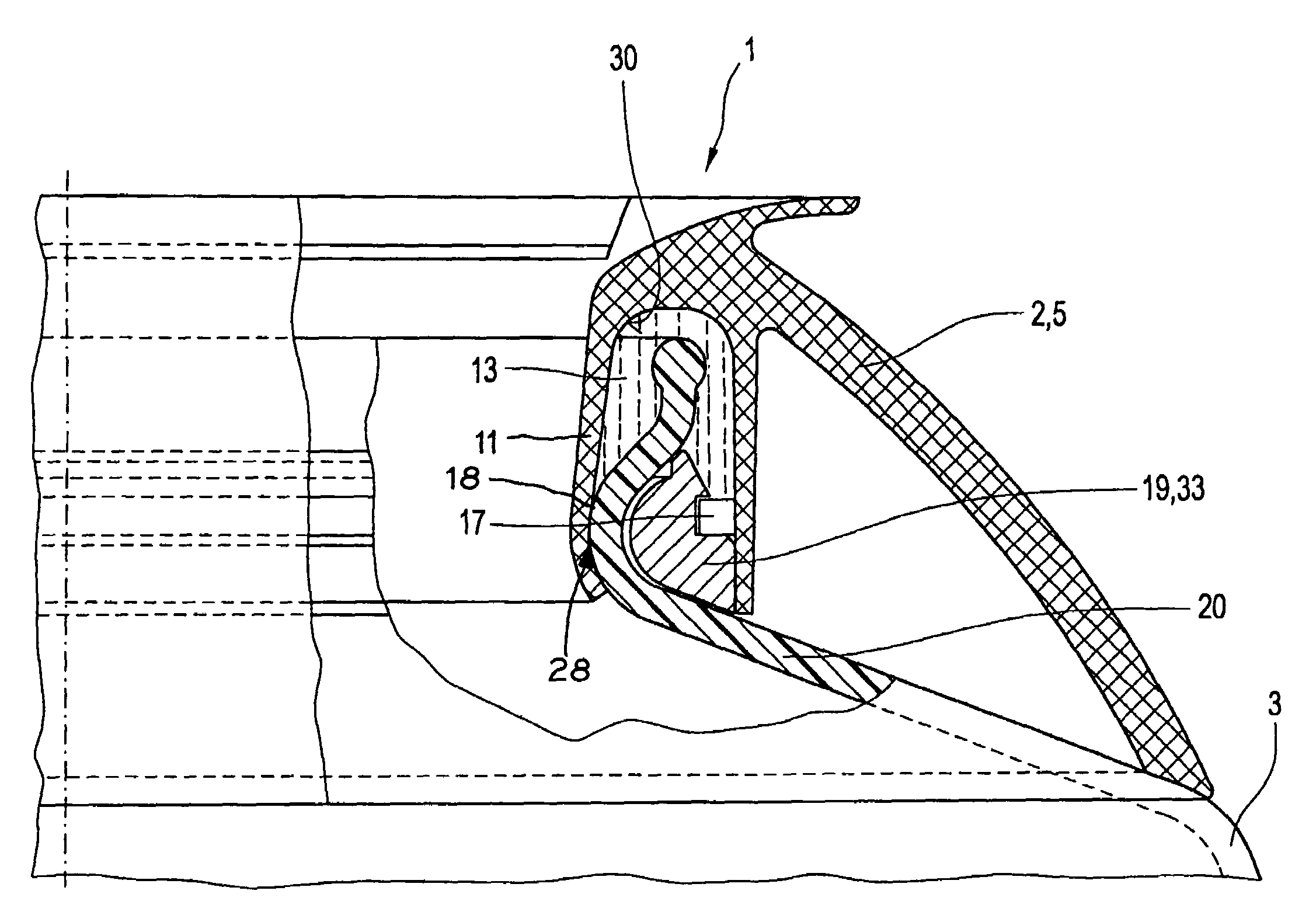
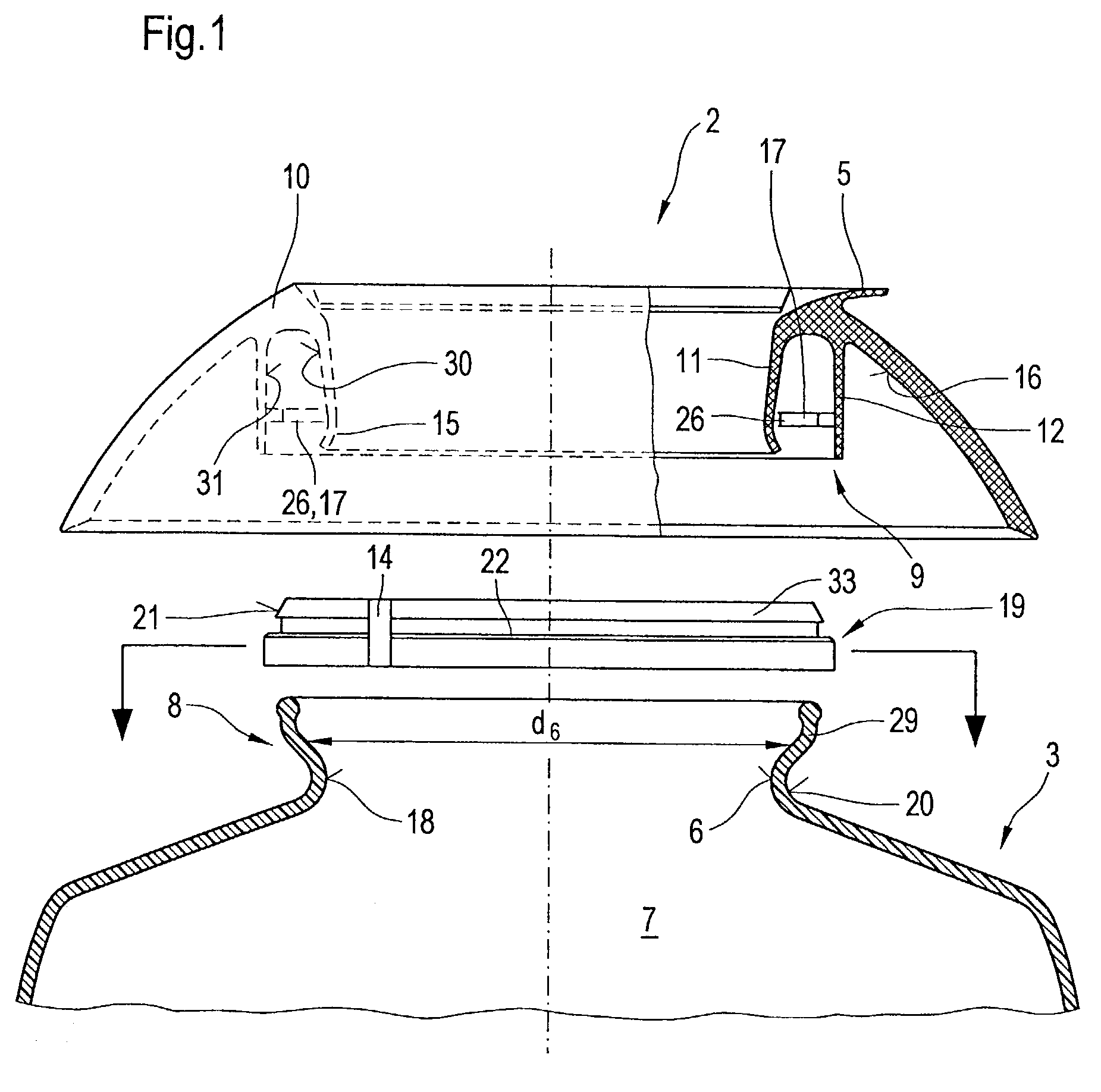
[0024]FIG. 1 illustrates in schematically greatly simplified presentation using lateral views and in part axial sections the basic structure of the individual elements for achieving a permanent bond 1 of a plastic fixture 2 on a glass container 3 in a view of the situation prior to assembly. If the glass container 3 is a coffeepot or teapot, the plastic fixture 2 is constructed in the shape of a pouring ring or pouring brim 5. In accordance with the purpose of the glass container 3 the plastic fixture 2 can also assume other forms.

[0025]The glass container 3 has an opening 6 for receiving and dispensing of filling fluid in and / or out of the interior 7 of the glass container 3. The glass container 3 is constructed in the vicinity of the opening with a lesser diameter d6 compared to the remaining interior 7. The area in which the opening 6 is arranged functions as a receiving and / or dispensing area is referred to as the opening area 8. This extends in functional location of the glass ...


PUM


Abstract

Bonding (1) of a plastic fixture (2) to a glass container (3), comprising a glass container (3) with an opening area (8) bearing an opening (6) and a plastic fixture (2) with two walls (11, 12) enclosing both sides of the wall (20) of the glass container (3) in the opening area in circumferential direction, a first inner wall (11) and a second outer wall (12). The opening area (8) has an area of lesser external dimensions on the outer circumference than on the opening (6). A wraparound element (19) interrupted in circumferential direction which encloses the opening area (8) in the vicinity of lesser cross-section and supports itself on the wall (20) of the glass container (3). The plastic fixture (2) is positively connected with the wraparound element (19).

Description

BACKGROUND OF THE INVENTION[0001]The invention relates to bonding of a plastic fixture on a glass container and further a procedure for achieving a permanent bond.[0002]Bondings of a plastic fixture with a glass container are known in a number of designs for various applications. One essential field of application in which such compounds are subject to great demands is the field of glass containers for holding and transporting liquids with very high or fluctuating temperatures, such as coffee or teapots. The plastic fixture of such containers is designed as a pouring element or pouring brim, which surrounds the wall of the glass container in the opening area and is attached to the glass container. As a rule polypropylene is used as a material. The attachment occurs in accordance with a first design mechanically as a rule by means of frictional connection. On the basis of the differing materials of the elements coming into contact with one another—glass container and plastic fixture—...

Claims


Application Information

Patent Timeline
Patent Type & Authority Patents(United States)
IPC IPC(8): B65D25/42A47G19/14A47J45/06
CPCA47J45/067A47G19/14
Inventor BECKER, ROLAND
Owner SCHOTT AG
Why Eureka
Try Eureka