Vehicle heating system

a heating system and vehicle technology, applied in vehicle heating/cooling devices, vehicle components, electrical devices, etc., can solve the problems of high frequency wave generation of wide-band modulated signals, heaters driven by pulse-wide-band modulated currents still suffer from other problems, and the voltage of pulse-wide-band modulated signals is problematic, so as to reduce costs

Inactive Publication Date: 2016-09-22
IEE INT ELECTRONICS & ENG SA
View PDF6 Cites 1 Cited by
  • Summary
  • Abstract
  • Description
  • Claims
  • Application Information

AI Technical Summary

Benefits of technology

The present invention is about a vehicle heating system that is more efficient and cost-effective than current systems. It includes a heating element, a power source, a control unit, and a DC / DC converter. The control unit regulates the power supplied to the heating element by adjusting the voltage, resulting in better heating control without the negative side effects of current methods. The DC / DC converter converts high-output DC voltage to low-output DC voltage, which reduces the amount of conductive material needed, resulting in less expensive and flexible cabling. Overall, this invention provides a more efficient and cost-effective vehicle heating system.

Problems solved by technology

A disadvantage of pulse width modulated signals is the generation of high frequency waves due to the quick switching between the “ON” state and the “OFF” state.
Even if the magnitude of such electro magnetic alternating fields can be kept low by the method as described in the patent application DE 10 2008 022 048 A1, heaters that are driven by pulse width modulated currents still suffer from other problems.
In particular the relation between the amplitude of the pulsed width modulated current, the voltage of the pulse width modulated signal and the resistance of the heating element is problematic for vehicle systems with a low-voltage power source.
Furthermore, the high current required for driving the heater may prevent the energy management system to drive other loads connected to the energy management system in parallel to the heater.
In the seat environment for instance, the energy management system is usually not sufficiently powerful to be able to drive the motors for seat positioning and the seat heater simultaneously.

Method used


Image

  • Vehicle heating system

Examples


Embodiment Construction

)

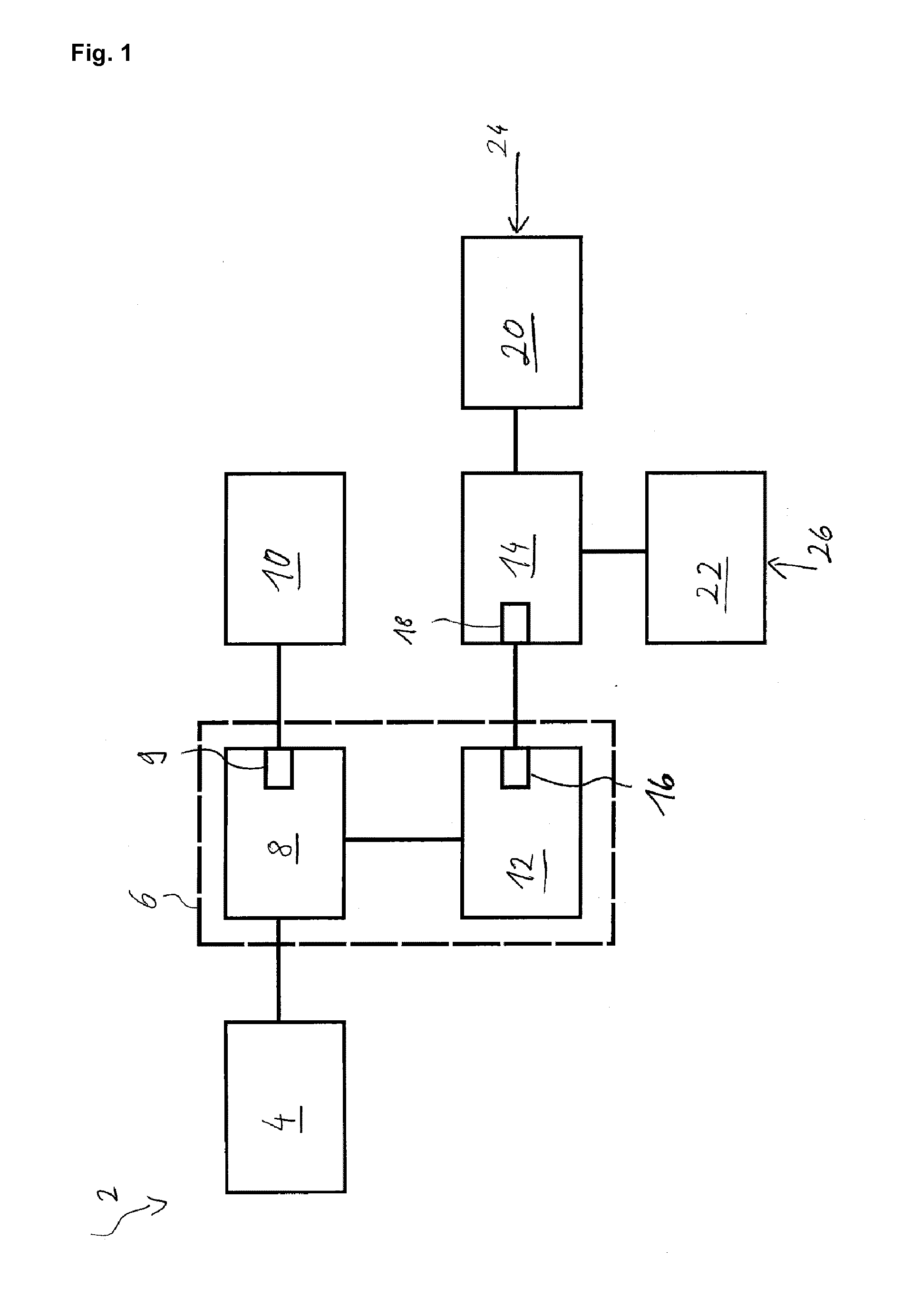
[0020]The vehicle heating system 2 according to the embodiment of FIG. 1 has a power source 4 that generates a direct current DC with an electrical power Pin. In this particular preferred embodiment of the invention, the power source can be 12 V lithium ion battery, a lithium polymer battery, a lead-acid battery or an alternator. The electrical power Pin with an input voltage Uin of 12 V and an input current Iin, is being inputted to a DC / DC converter 8 of a control unit 6. The DC / DC converter 8 outputs an output voltage supply Usupply between 3 V to 40 V to the foil based seat heater 10.

[0021]For instance, for high power operation i.e. if high heating power is required, the output voltage supply Usupply is greater than the voltage of the input DC Uin. On the other hand, for low power operation, i.e. if a lower heating power is required, the output voltage supply Usupply may be adjusted to values which are lower than the 12 V input voltage Uin.

[0022]The course of the output voltage...


PUM


Abstract

A vehicle heating system that includes a heating element and a power source for providing an electrical power to the heating element. Furthermore, the vehicle heating system includes a control unit, which is operatively coupled to the power source and / or the heating element. The control unit is adapted to regulate the electrical power to be supplied to the heating element over time and the control unit is configured to regulate the electrical power by modifying a DC voltage supply Usupply supplied to the heating element over time. The heat provided by the heating element is preferably in linear relationship with the DC voltage supply Usupply supplied to the heater.

Description

TECHNICAL FIELD[0001]The present invention generally relates to a vehicle heating system. More specifically the invention relates to a vehicle heating system that is controlled by a DC (direct current) voltage supply provided by a control unit.BACKGROUND ART[0002]Driving heating elements, such as seat heater elements, with pulse width modulated (PWM) currents is a standard in today's automotive industry. Heating elements more particularly seat heaters are turned “ON” or “OFF” in relation to the pulsed current supplied to the heating element by the control unit. The control unit most commonly comprises a semiconductor switch that switches between the “ON” state and the “OFF” state at a predefined switching frequency. The longer the width of the pulse or the more often (in a set time interval) the amplitude of the PWM current is provided, the more electrical power is delivered in average to the heating element and consequently the more heat is generated.[0003]A disadvantage of pulse w...

Claims


Application Information

Patent Timeline
IPC IPC(8): H05B1/02B60H1/00
CPCH05B1/0236B60H1/00642B60H1/00271H05B1/0202H05B1/0238
Inventor PETEREIT, ANDREASWENDT, CHRISTOPH
Owner IEE INT ELECTRONICS & ENG SA
Why Eureka
Try Eureka