
Device for clarifying exhaust gas from internal combustion engine

a technology for exhaust gas and internal combustion engines, which is applied in the direction of physical/chemical process catalysts, separation processes, metal/metal-oxide/metal-hydroxide catalysts, etc., and can solve the problem of high manufacturing cos

Inactive Publication Date: 2007-01-02
HONDA MOTOR CO LTD
View PDF19 Cites 6 Cited by
  • Summary
  • Abstract
  • Description
  • Claims
  • Application Information

AI Technical Summary

Benefits of technology

[0004]Accordingly, it is an object of the present invention to provide an exhaust emission control system of the above-described type, wherein the amount of noble metal-based three-way catalyst used can be decreased to provide a reduction in manufacture cost, and the exhaust emission control rate can be maintained high.

Problems solved by technology

However, the exhaust emission control system suffers from a problem that the manufacture cost is high due to the use of the noble metal-based three-way catalyst.

Method used


Image

  • Device for clarifying exhaust gas from internal combustion engine
  • Device for clarifying exhaust gas from internal combustion engine
  • Device for clarifying exhaust gas from internal combustion engine

Examples


first embodiment

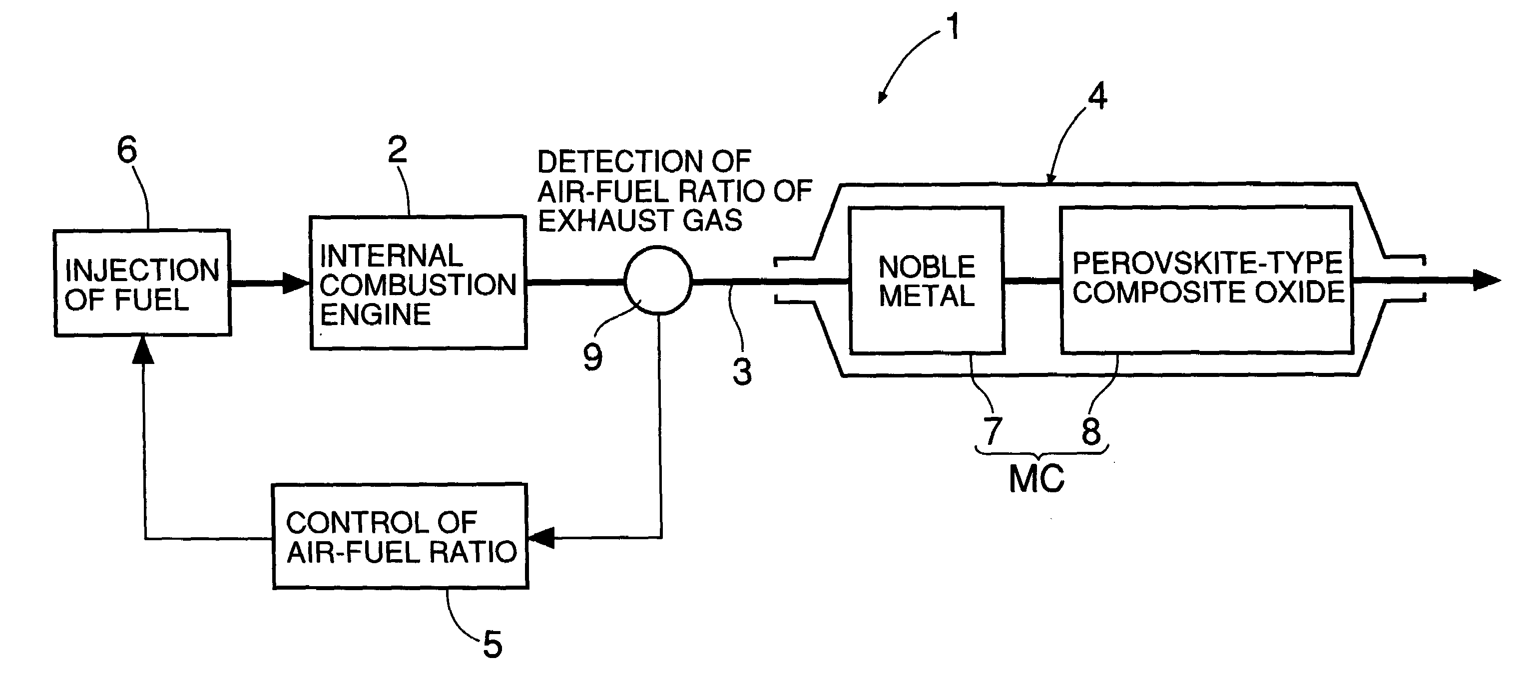
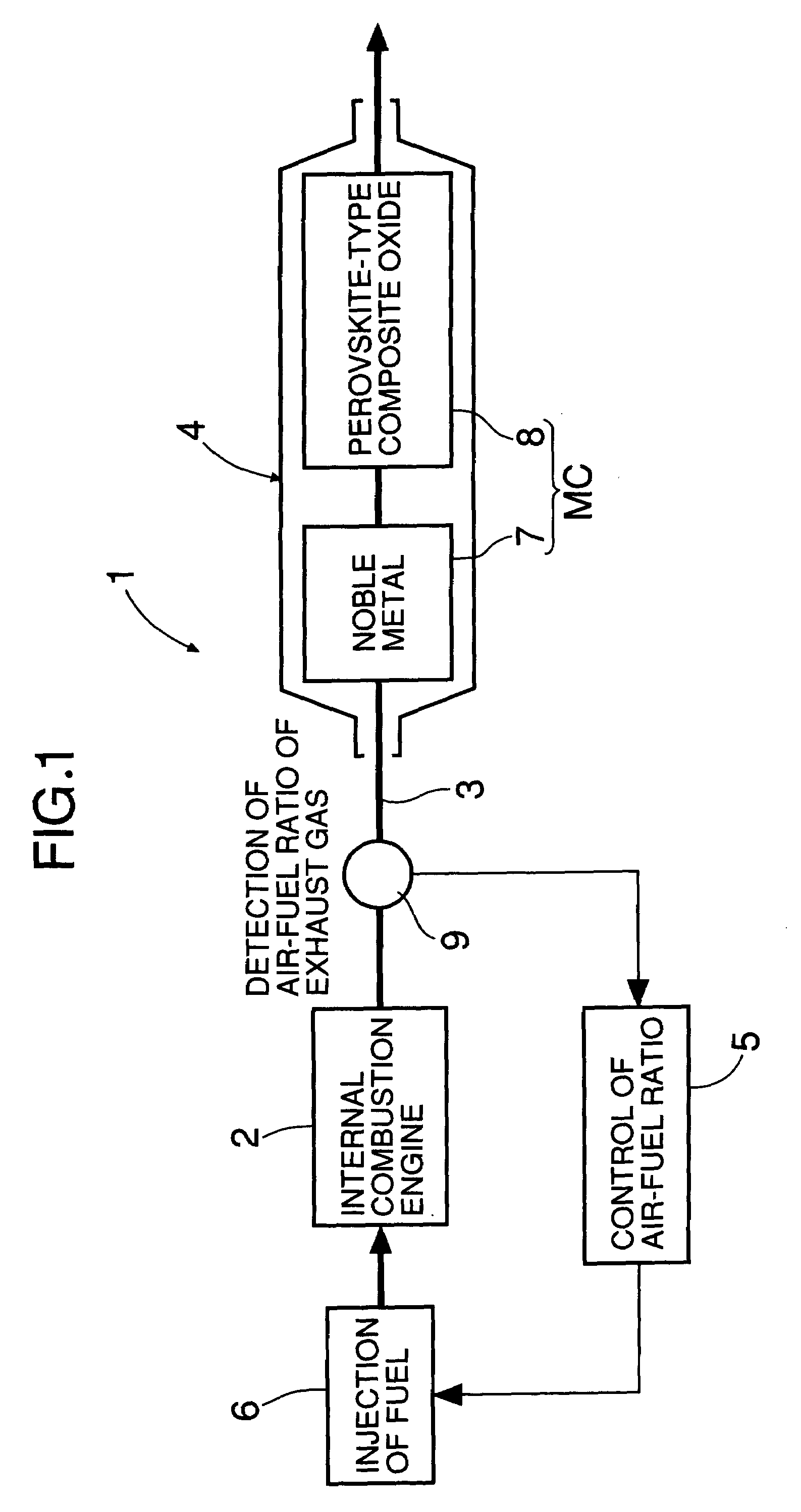
[0028]In the first embodiment shown in FIG. 1, an exhaust emission control system 1 includes an exhaust gas purification device 4 disposed in an exhaust pipe 3 of an internal combustion engine 2, and an air-fuel ratio control device 5 for controlling the air-fuel ratio (A / F) of an air / fuel mixture supplied to the internal combustion engine 2. A fuel injection device 6 injects into the internal combustion engine 2 an amount of fuel determined based on a control signal from the air-fuel ratio control device 5.

[0029]The exhaust gas purification device 4 comprises a monolith catalyst MC that includes an oxygen storage agent (OSC agent) and a noble metal-based three-way catalyst comprising Pd, Rh, and Pt disposed at an upstream location in the exhaust gas flow, that is, the exhaust pipe 3, and that includes a perovskite-type double oxide having three-way catalytic function disposed at a downstream location in the exhaust gas flow, that is, the exhaust pipe 3. With regard to this monolith...

second embodiment

[0056]FIG. 8 shows a In this exhaust emission control system, a first catalyst section 7 is used mainly to regulate the air-fuel ratio of exhaust gas that is to be introduced into a second catalyst section 8. Purification of the exhaust gas is carried out mainly by the second catalyst section 8. In this case, the first catalyst section 7 can be constructed at a small size, whereby the amount of noble metal-based three-way catalyst used can be decreased.

third embodiment

[0057]FIG. 9 shows a In this exhaust emission control system, a first catalyst section 7 is constructed at a small size and disposed in an exhaust pipe 3 at a location immediately downstream of an internal combustion engine 2. With this construction, the first catalyst section 7 is activated soon after starting the engine and exhibits an exhaust emission control capability. After the engine is warmed up, the first catalyst section 7 is used to regulate the air-fuel ratio of exhaust gas that is to be introduced into a second catalyst section 8, and purification of the exhaust gas is thus conducted solely by the second catalyst section 8.

[0058]It is also possible to separate the Pd, Rh, and Pt such that Pd is disposed at a location upstream in the exhaust gas flow and Rh and Pt are disposed at a location downstream therein. In order to widen the A / F Window of the perovskite-type double oxide even to a slight extent, adding a small amount of a noble metal such as Pd, Rh, or Pt to the ...


PUM

PropertyMeasurementUnit
atomic numbersaaaaaaaaaa

Abstract

An exhaust emission control system for an internal combustion engine is provided. The exhaust emission control system (4) includes a monolith catalyst (MC) that includes an oxygen storage agent and a noble metal-based three-way catalyst including Pd, Rh, and Pt disposed at an upstream location in the exhaust gas flow in the internal combustion engine (2), and a perovskite-type double oxide having a three-way catalytic function disposed at a downstream location in the exhaust gas flow. The amount C1 of Pd carried is 0.97 g / L≦C1≦1.68 g / L, the amount C2 of Rh carried is 0.11 g / L≦C2≦0.2 g / L, the amount C3 of Pt carried is 0.06 g / L≦C3≦0.11 g / L, the amount C4 of the oxygen storage agent carried is 25 g / L≦C4≦75 g / L, and the amount C5 of the perovskite-type double oxide carried is 5 g / L≦C5≦15 g / L. It is thereby possible to provide an exhaust emission control system that can reduce the production cost by reducing the amount of noble metal-based three-way catalyst used and at the same time can maintain a high exhaust emission control rate.

Description

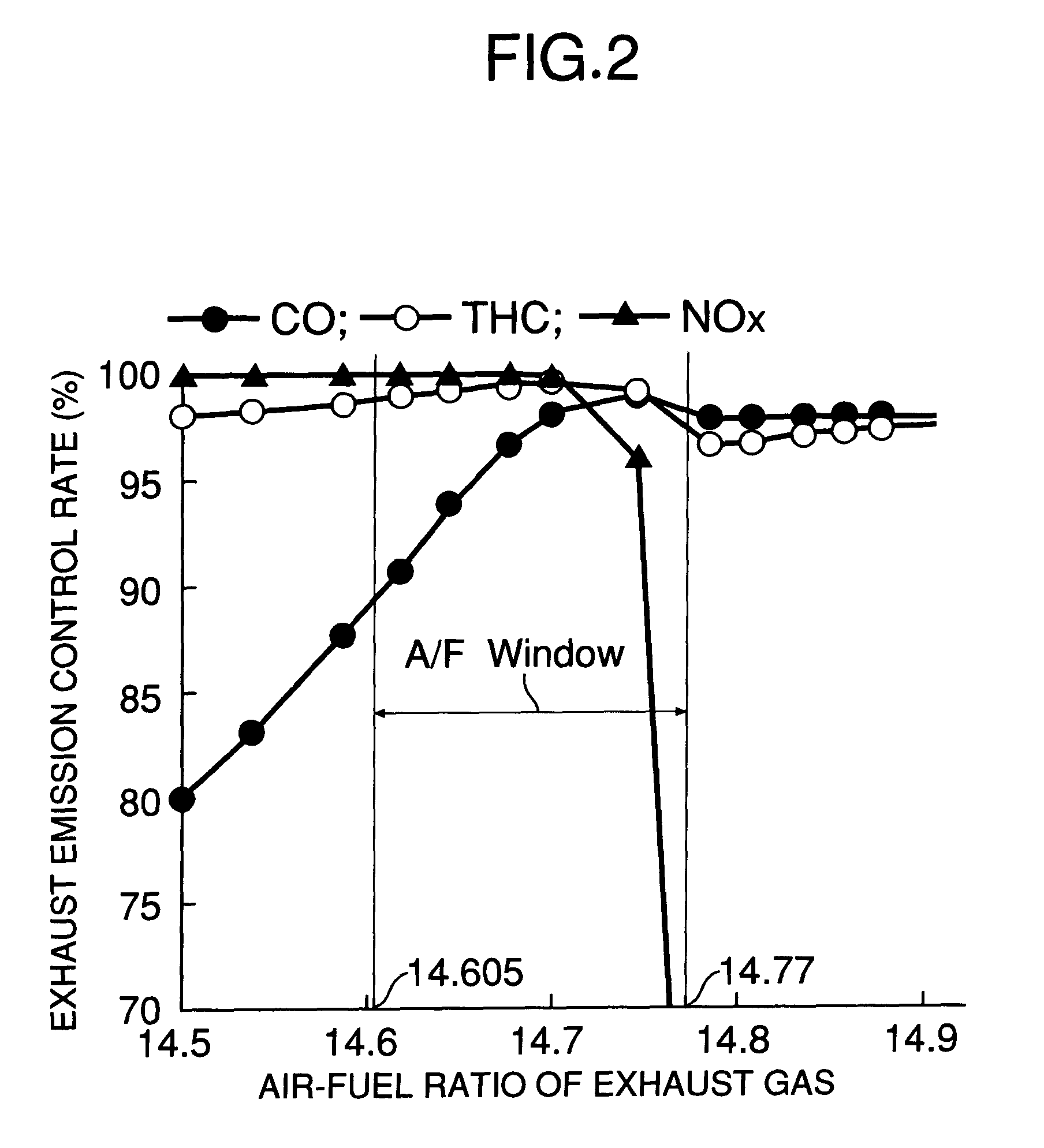
FIELD OF THE INVENTION[0001]The present invention relates to an exhaust emission control system for an internal combustion engine.BACKGROUND ART[0002]There is a conventionally known exhaust emission control system used for an exhaust system of an internal combustion engine in which an air / fuel mixture is controlled to have a theoretical air-fuel ratio, the exhaust emission control system employing a three-way catalyst comprising noble metals such as Pt, Rh, and Pd, that is, a noble metal-based three-way catalyst.[0003]In the noble metal-based three-way catalyst, a range of air-fuel ratio enabling a high exhaust emission control rate to be obtained, namely, an A / F window is wide. Therefore, an exhaust emission control system using a noble metal-based three-way catalyst has an advantage that the control of an air-fuel ratio for increasing the exhaust emission control rate is relatively easy to carry out. However, the exhaust emission control system suffers from a problem that the manu...

Claims


Application Information

Patent Timeline
Patent Type & Authority Patents(United States)
IPC IPC(8): B01J23/40B01J23/00F01N3/10B01D53/86B01D53/94B01J23/02B01J23/10B01J23/34B01J23/46B01J23/63B01J35/00F01N3/28
CPCB01D53/945B01J23/002B01J23/464B01J23/63B01J35/0006B01D53/9472Y02T10/22B01D2255/1021B01D2255/1023B01D2255/1025B01D2255/402B01D2255/908B01J23/02B01J23/10B01J23/34B01J2523/00B01J2523/3712B01J2523/48B01J2523/822B01J2523/824B01J2523/828Y02T10/12B01J35/19
Inventor SUZUKI, NORIHIKOUEDAHIRA, HIDEKIOONO, HIROSHIKIKUCHI, SHINICHISAKANUSHI, MASAHIROYAMADA, RYOKOMATSUZONO, YOSHIAKI
Owner HONDA MOTOR CO LTD
Learn More