Anisotropic conductive film
a technology conductive film, which is applied in the direction of coupling device connection, semiconductor/solid-state device details, instruments, etc., can solve the problem of insufficient application of anisotropic conductive film to a narrow pitch terminal of a connection target (electronic components, circuit boards), and the distance between adjacent conductive paths becomes too large, and achieves high reliability
- Summary
- Abstract
- Description
- Claims
- Application Information
AI Technical Summary
Benefits of technology
Problems solved by technology
Method used
Image
Examples
example 1
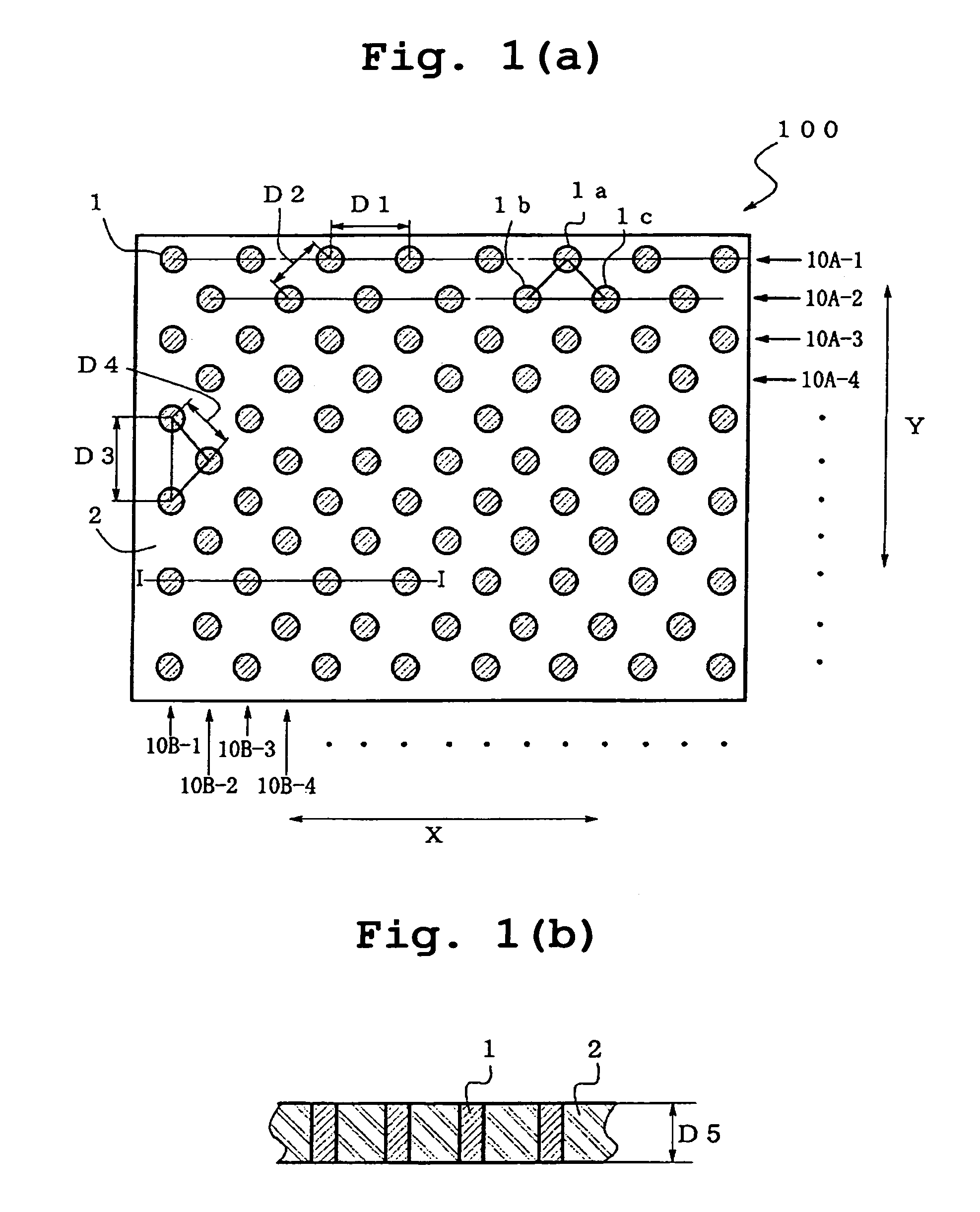
[0143]An aluminum cylindrical core having a diameter of 320 mm and a length of 270 mm is set on a horizontal type regular winding machine (HPW-02, Nittoku Engineering Co., Ltd.), on which a 50 μm-thick fluorocarbon resin film as a slip film and a film consisting of a 50 μm-thick thermoplastic polyurethane elastomer having a rubber hardness of 75 degrees (Esmer URS, Nihon Matai Co., Ltd., softening temperature 60° C.) were wound, and a heat-resistant polyurethane coated wire (copper wire (diameter 25 μm) coated with heat resistant polyurethane in 2 μm thickness) having a diameter of 29 μm was wound 250 mm at a winding intervals (pitch) of 100 μm. Then, after winding a thermoplastic polyurethane elastomer film similar to the above, winding of heat resistant polyurethane coated wire was further repeated 54 times, during which the odd-numbered layers of wound wires and even-numbered layers of wound wires from the core side were displaced such that the start position of the insulation wi...
example 2
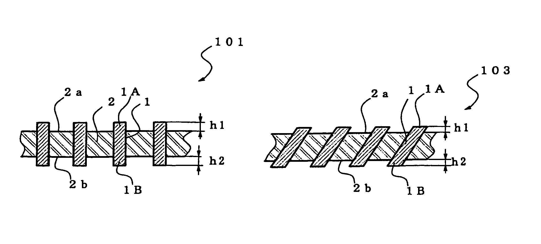
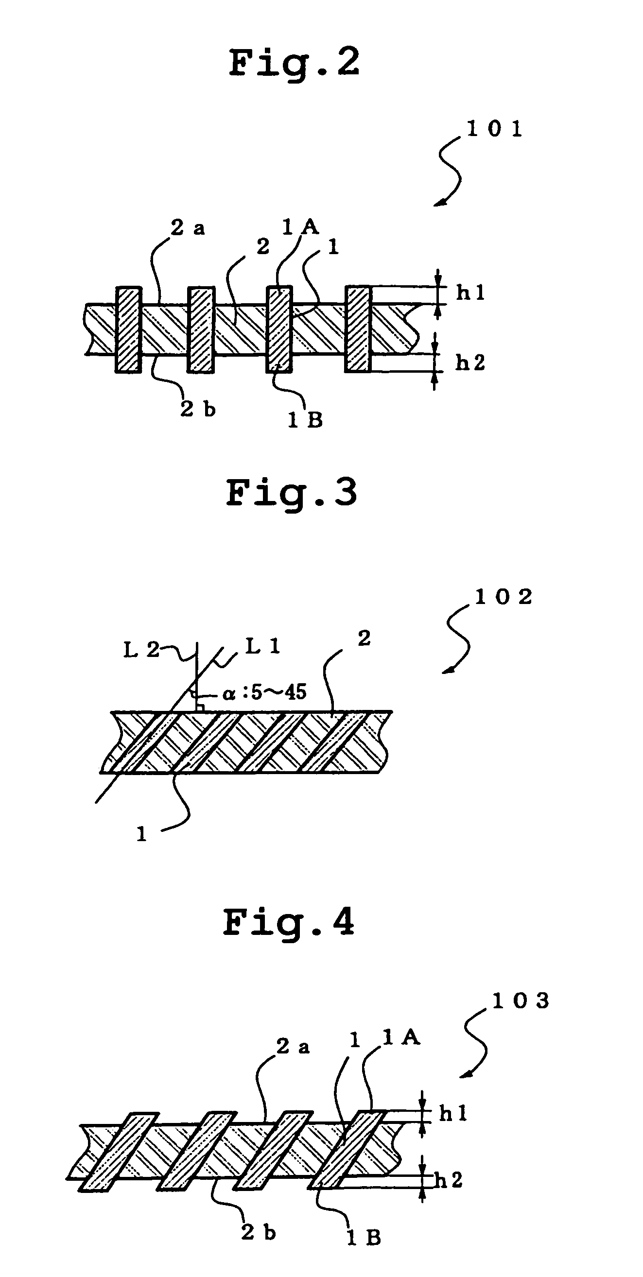
[0148]Using an APS (Advanced Plasma, Co., Ltd, reactive ion plasma system), the sections (both sides) of the anisotropic conductive film prepared in Example 1 were treated using CF4 as etching gas at a power of 2000 W and a gas flow of 0.5 L / min for 30 min to prepare an anisotropic conductive film in which the end of the conductive path is protruded from both principal planes of the film substrate for 15 μm. The modulus of elasticity of the anisotropic conductive film at 25–40° C. was 16–18 MPa.
example 3
[0149]Using APS (Advanced Plasma, Co., Ltd, reactive ion plasma system), one side of the section of the anisotropic conductive film prepared in Example 1 was treated using CF4 as etching gas at a power of 2000 W and a gas flow of 0.5 L / min for 30 min, so that the end of the conductive path was protruded from the principal plane of the film substrate (principal plane facing the circuit board) for 15 μm, and the other side of the section was treated using CF4 as etching gas at a power of 2000 W and a gas flow of 0.5 L / min for 60 min, so that the end of the conductive path was protruded from the principal plane of the film substrate (principal plane facing the electronic component) for 30 μm, whereby an anisotropic conductive film having a different protrusion amount at the end of the conductive path from each principal plane of the film was prepared. The modulus of elasticity of the anisotropic conductive film at 25–40° C. was 15–17 MPa.
PUM
| Property | Measurement | Unit |
|---|---|---|
| outer diameter | aaaaa | aaaaa |
| outer diameter | aaaaa | aaaaa |
| angle | aaaaa | aaaaa |
Abstract
Description
Claims
Application Information
 - R&D
- Intellectual Property
- Life Sciences
- Materials
- Tech Scout
- Unparalleled Data Quality
- Higher Quality Content
- 60% Fewer Hallucinations
Browse by: Latest US Patents, China's latest patents, Technical Efficacy Thesaurus, Application Domain, Technology Topic, Popular Technical Reports.
© 2025 PatSnap. All rights reserved.Legal|Privacy policy|Modern Slavery Act Transparency Statement|Sitemap|About US| Contact US: help@patsnap.com


