
Camera calibration system using planar concentric circles and method thereof

a calibration system and camera technology, applied in the field of camera calibration systems, can solve the problems of reducing the reliability of calibration, difficult to manufacture and maintain the calibration object of a rectangular parallelepiped, and difficulty in exact calculation of the camera's intrinsic parameters, so as to increase the reliability of calibration

Inactive Publication Date: 2006-12-26
KOREA ADVANCED INST OF SCI & TECH
View PDF11 Cites 19 Cited by
  • Summary
  • Abstract
  • Description
  • Claims
  • Application Information

AI Technical Summary

Benefits of technology

This method simplifies camera calibration by using easily manufactured 2D patterns, reducing complexity and improving reliability by calculating intrinsic parameters without requiring precise point correspondence, and is effective in determining accurate camera calibration values.

Problems solved by technology

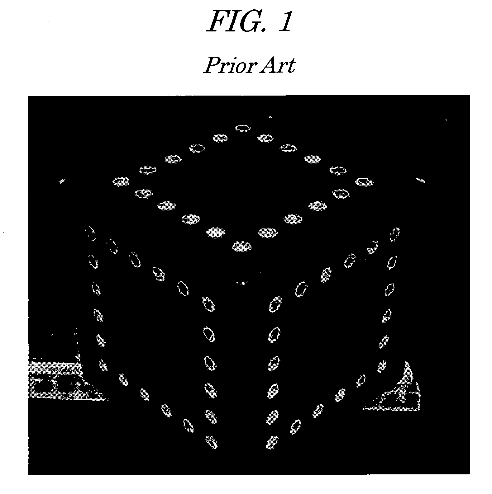
However, in the first method of calibrating a camera using a 3D artificial calibration object, it is difficult to manufacture and maintain the calibration object of a rectangular parallelepiped.
Otherwise, exact calculation of the camera's intrinsic parameters become difficult and the reliability of calibration is degraded accordingly.
Although this self calibration method can be widely applied without the limitation of using an artificial calibration object, it is difficult to exactly define the corresponding points.
Due to this, this method has problems that the process of finding a solution is very complicated and it is also difficult to find a correct solution.
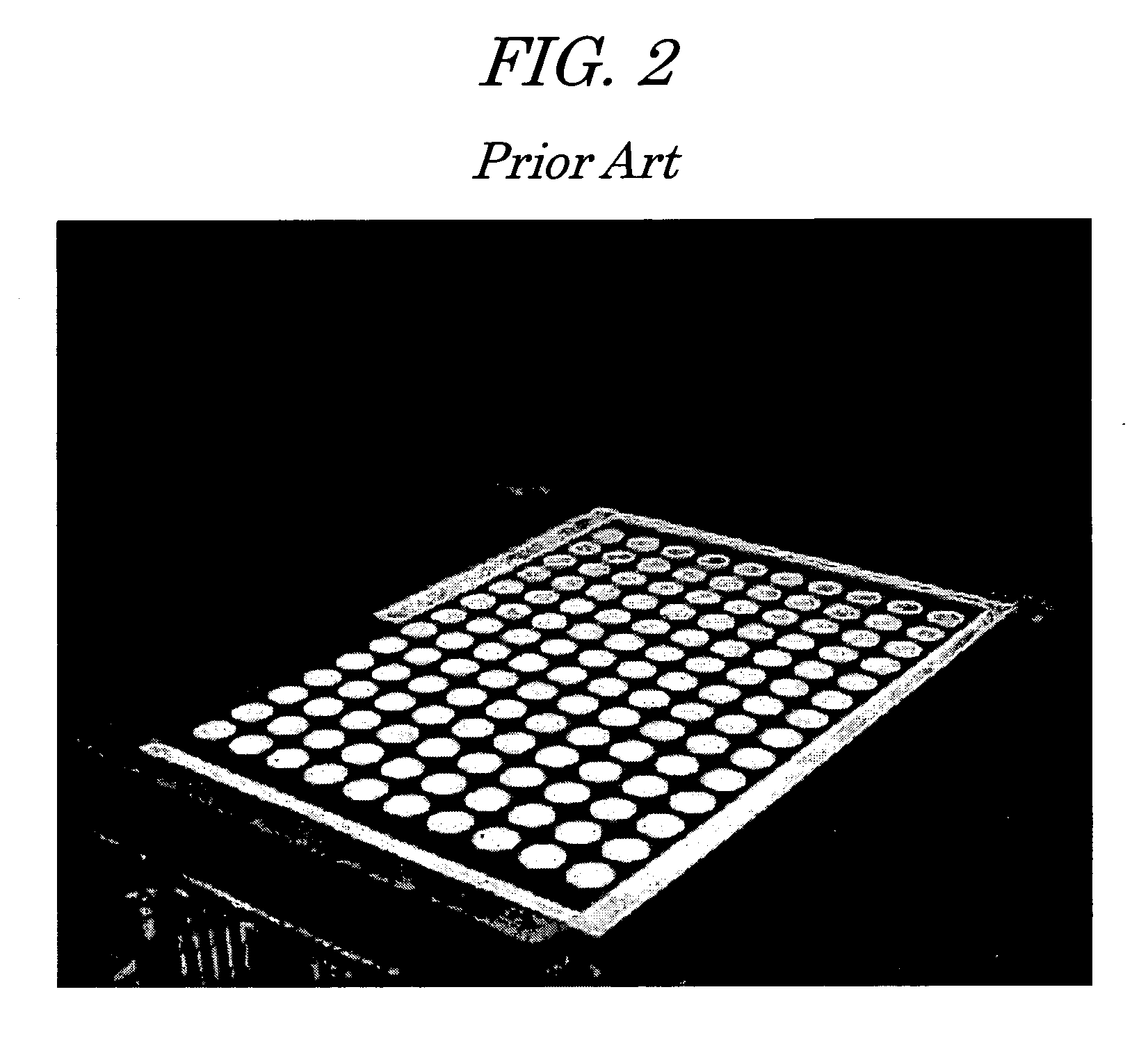
However, this method is very complicated since it must use a plurality of calibration points of the images of a plane and compare them to each other.

Method used


Image

  • Camera calibration system using planar concentric circles and method thereof
  • Camera calibration system using planar concentric circles and method thereof
  • Camera calibration system using planar concentric circles and method thereof

Examples


experimental example

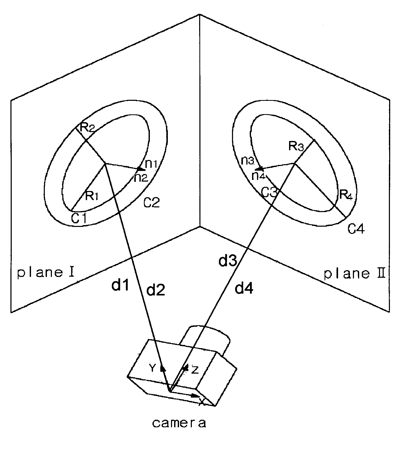
[0075]A concentric circle is drawn on the plane so that the central points of two circles having a radius of 40 mm and 80 mm, respectively are located at one point. Also, as shown in FIG. 4a and FIG. 4b, image of the circle is taken at two different angles to obtain two images. An XC-003 camera manufactured by SONY, with a focal radius of 8 mm was used.

[0076]After obtaining two projection images (containing the boundary lines), a calibration value as shown in Table 1 is obtained by means of a camera calibration method using the concentric circle pattern according to the present invention.

[0077]

TABLE 1ClassuOvOαuαvComparative example306.70240.441104.21112.5(Z. Zhang)Embodiment of the309.37246.011104.71110.7present invention

[0078]The comparative example (Z. Zhang) in Table 1 shows the calibrated values according to the camera calibration method taught in an article Z. Zhang, “Flexible Camera Calibration by Viewing a Plane From Unknown Orientations”, In Proc. 7th International Conferen...


PUM


Abstract

The invention relates to a camera calibration system and method thereof which is capable of easily performing camera calibration using a concentric circle pattern. According to the invention, a method of calibrating a camera calibrates the intrinsic parameters of the camera required to measure geometric information of an object using projection invariable characteristics of concentric circles. The method includes the steps of taking images of the calibration pattern consisting of two or more concentric circles located in the same plane and having different radius at different angles to obtain projected images calculating the central point of the projected images using a given algorithm, and calculating the principal point and focal point of camera using a nonlinear minimization algorithm based on the central point thus obtained.

Description

CROSS-REFERENCE TO RELATED APPLICATIONS[0001]This application is a continuation-in-part of application Ser. No. 09 / 919,086, filed Jul. 31, 2001 now abandoned , entitled “Camera Calibration System Using Planar Concentric Circles and Method Thereof”, the contents of which are incorporated herein in their entirety.TECHNICAL FIELD[0002]The invention relates generally to a method of calibrating a camera for obtaining the camera's intrinsic parameters required when the camera is used to obtain geometric information. More particularly, the invention relates to a camera calibration system and method thereof, which uses a concentric circle pattern as an artificial calibration pattern in the process of calibrating the camera to obtain the camera's intrinsic parameters by analyzing two images of the concentric circle pattern taken at different angles.BACKGROUND OF THE INVENTION[0003]To obtain geometric information of an object using a camera, it is required to calibrate the camera by estimatin...

Claims


Application Information

Patent Timeline
Patent Type & Authority Patents(United States)
IPC IPC(8): G06K9/00H04N5/232G06T7/00H04N17/00
CPCG06T7/0018H04N17/002G06T7/80
Inventor KIM, JUN-SIKKWEON, IN-SO
Owner KOREA ADVANCED INST OF SCI & TECH
Learn More