
Method of determining performance of RFID devices

a technology of radio frequency identification and performance measurement, which is applied in the direction of burglar alarm mechanical actuation, burglar alarm by hand-portable object removal, instruments, etc., can solve the problems of affecting testing, process cannot support a high volume manufacturing environment, and requires a relatively large space for testing

Active Publication Date: 2006-12-26
AVERY DENNISON CORP
View PDF123 Cites 70 Cited by
  • Summary
  • Abstract
  • Description
  • Claims
  • Application Information

AI Technical Summary

Benefits of technology

"The invention is a method for predicting or determining the performance of an RFID device by using near-field testing results to predict far-field performance. This allows for better understanding and optimization of RFID device performance. The method can be used to predict parameters such as range, margin, sensitivity, frequency performance, read sensitivity, write sensitivity, peak operating frequency, and average sensitivity over a given frequency band. The invention also includes performing near-field testing on the RFID device and determining its far-field performance from the test results. Overall, the invention provides a more efficient and effective way to develop and optimize RFID devices."

Problems solved by technology

There are several potential problems with this sort of testing.
First, such testing requires a relatively large space.
Second, the process does not support a high volume manufacturing environment.
Third, the results of such testing may be affected by a variety of factors, such as changes in the environment around the tested RFID device.
Thus, it will be appreciated that performing such testing on closely spaced devices, such as devices on a sheet or a roll, may be impractical and / or expensive.

Method used


Image

  • Method of determining performance of RFID devices
  • Method of determining performance of RFID devices
  • Method of determining performance of RFID devices

Examples


Embodiment Construction

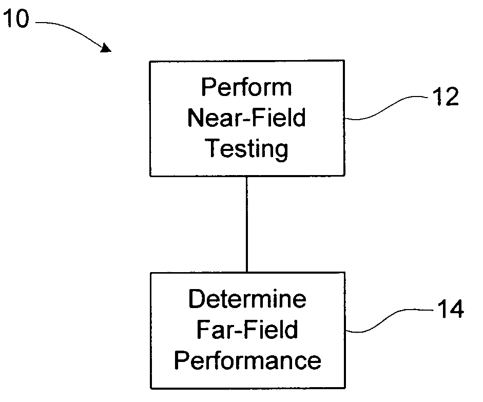
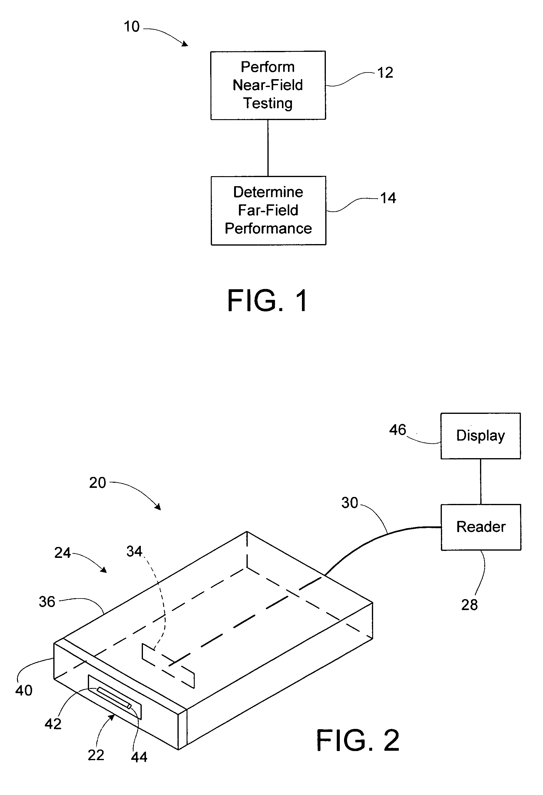
[0019]A method of determining far-field performance of an RFID device, such as in or on a tag, label, package, film, carton, wrap, or a portion of any of these, includes performing near-field testing or measurement of the RFID device, and determining or predicting far-field performance based on the results of the near-field testing or measurement. The determining or predicting of far-field performance may involve calculating a measure of far-field performance based on near-field results or measurements. Alternatively, a prediction of the far-field performance may be obtained from other sources, such as from a look-up table based on prior correlations between near-field test results or measurements, and far-field results. The predicted far-field performance may include any of a variety of performance factors, including range, sensitivity, frequency performance, read sensitivity, write sensitivity, peak operating frequency, and / or average sensitivity over a given frequency band. Using...


PUM


Abstract

A method of determining far-field performance of an RFID device, such as in or on a tag, label, package, film, carton, wrap, or a portion of any of these, includes performing near-field testing or measurement of the RFID device, and determining or predicting far-field performance based on the results of the near-field testing or measurement. The determining or predicting of far-field performance may involve calculating a measure of far-field performance based on near-field results or measurements. The predicted far-field performance may include any of a variety of performance factors, including range, sensitivity, frequency performance, read sensitivity, write sensitivity, peak operating frequency, and / or average sensitivity over a given frequency band. Using near-field testing results to predict far-field performance may allow use of compact testing facilities, in situ testing of RFID devices, and / or faster and / or less costly testing of RFID devices.

Description

BACKGROUND OF THE INVENTION[0001]1. Field of the Invention[0002]This invention relates to the field of radio frequency identification (RFID) devices, and specifically to methods for determining or predicting performance of such RFID devices.[0003]2. Description of the Related Art[0004]Radio frequency identification (RFID) tags and labels (collectively referred to herein as “devices”) are widely used to associate an object with an identification code. RFID devices generally have a combination of antennas and analog and / or digital electronics, which may include for example communications electronics, data memory, and control logic. For example, RFID tags are used in conjunction with security locks in cars, for access control to buildings, and for tracking inventory and parcels. Some examples of RFID tags and labels appear in U.S. Pat. Nos. 6,107,920, 6,206,292, and 6,262,692, all of which are hereby incorporated by reference in their entireties.[0005]As noted above, RFID devices are g...

Claims


Application Information

Patent Timeline
Patent Type & Authority Patents(United States)
IPC IPC(8): G01R31/302G08B13/14
CPCG01R29/08G01R31/303G06K7/0095
Inventor WEAKLEY, T. CRAIGFORSTER, IAN J.
Owner AVERY DENNISON CORP
Learn More