
Systems and methods for placing materials into bone

a technology of materials and bone, applied in the field of bone condition treatment, can solve the problems of little opportunity to quickly and accurately adjust the cement flow, the injection volume or the injection rate cannot be adjusted or controlled in real time, and the targeted bone interior can suddenly overfill, so as to achieve greater control over the placement of materials into bon

Inactive Publication Date: 2006-12-26
ORTHOPHOENIX
View PDF74 Cites 495 Cited by
  • Summary
  • Abstract
  • Description
  • Claims
  • Application Information

AI Technical Summary

Benefits of technology

[0008]One aspect of the invention provides an instrument for tamping material into bone through a subcutaneous path. The instrument comprises a body having a length and a terminus. The body includes markings located along the length at increments from the terminus. The markings allow the physician to gauge the position of the instrument in the subcutaneous path, as material is being tamped into bone. In particular, the markers allow the physician to tell at a glance the location of the terminus, in terms of how far beyond or short of the end of the subcutaneous path it is.

Problems solved by technology

Conventional cement injection devices provide no opportunity to override the spring action and quickly terminate the flow of cement, should the cavity fill before the spring-spring-actuated. mechanism is triggered, conventional cement injection devices do not permit the injection volume or inject rate to be adjusted or controlled in real time, in reaction to cancellous bone volume and density conditions encountered inside bone.
Because high pressure is used, there is little opportunity to quickly and accurately adjust cement flow in reaction to bone volume and density conditions encountered.
As a result of the relatively high pressure that conventional procedures rely upon, coupled with the effective lack of a short response time, the targeted bone interior can suddenly overfill.

Method used


Image

  • Systems and methods for placing materials into bone
  • Systems and methods for placing materials into bone
  • Systems and methods for placing materials into bone

Examples


Embodiment Construction

[0060]Although the disclosure hereof is detailed and exact to enable those skilled in the art to practice the invention, the physical embodiments herein disclosed merely exemplify the invention which may be embodied in other specific structure. While the preferred embodiment has been described, the details may be changed without departing from the invention, which is defined by the claims.

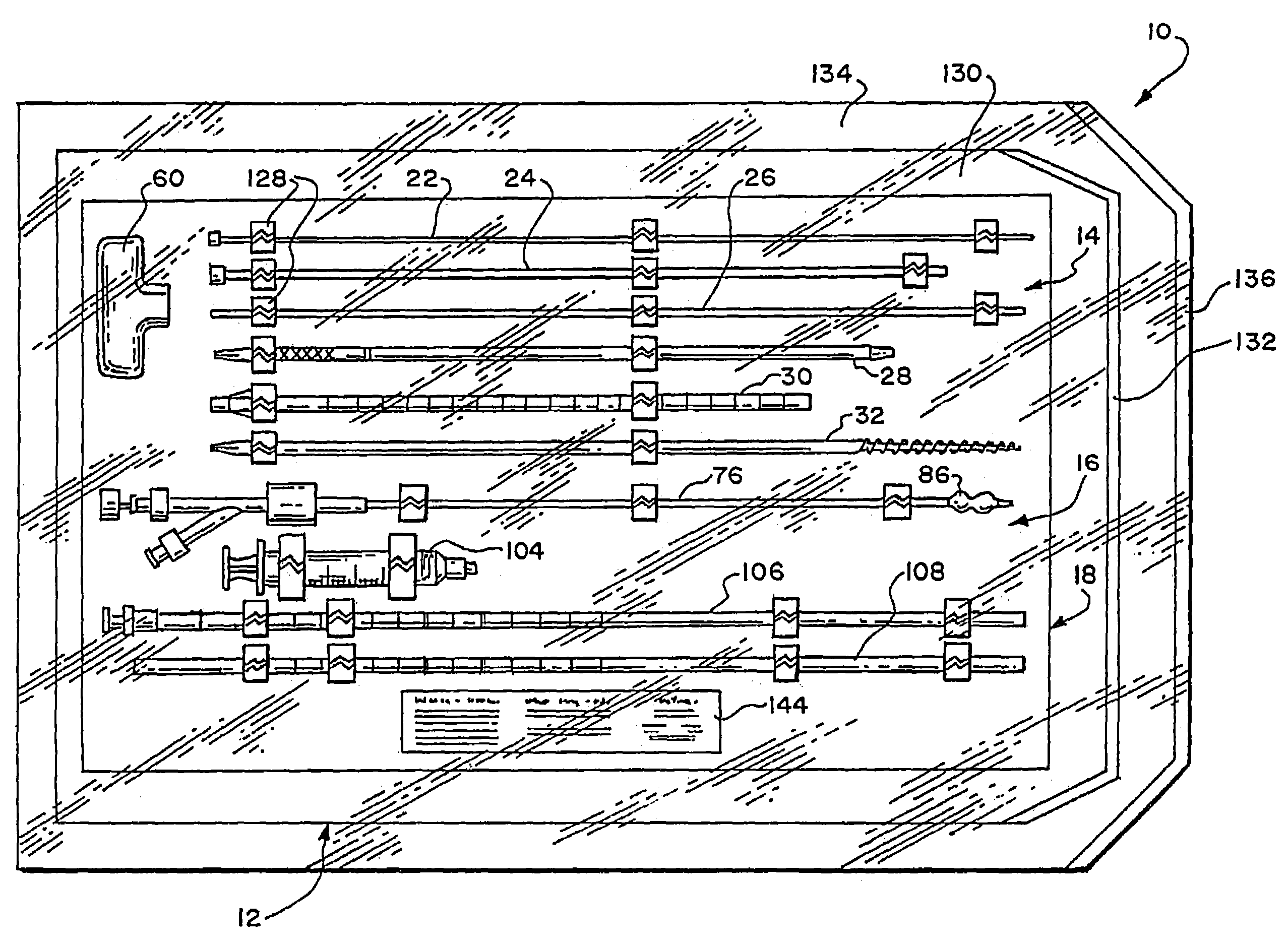
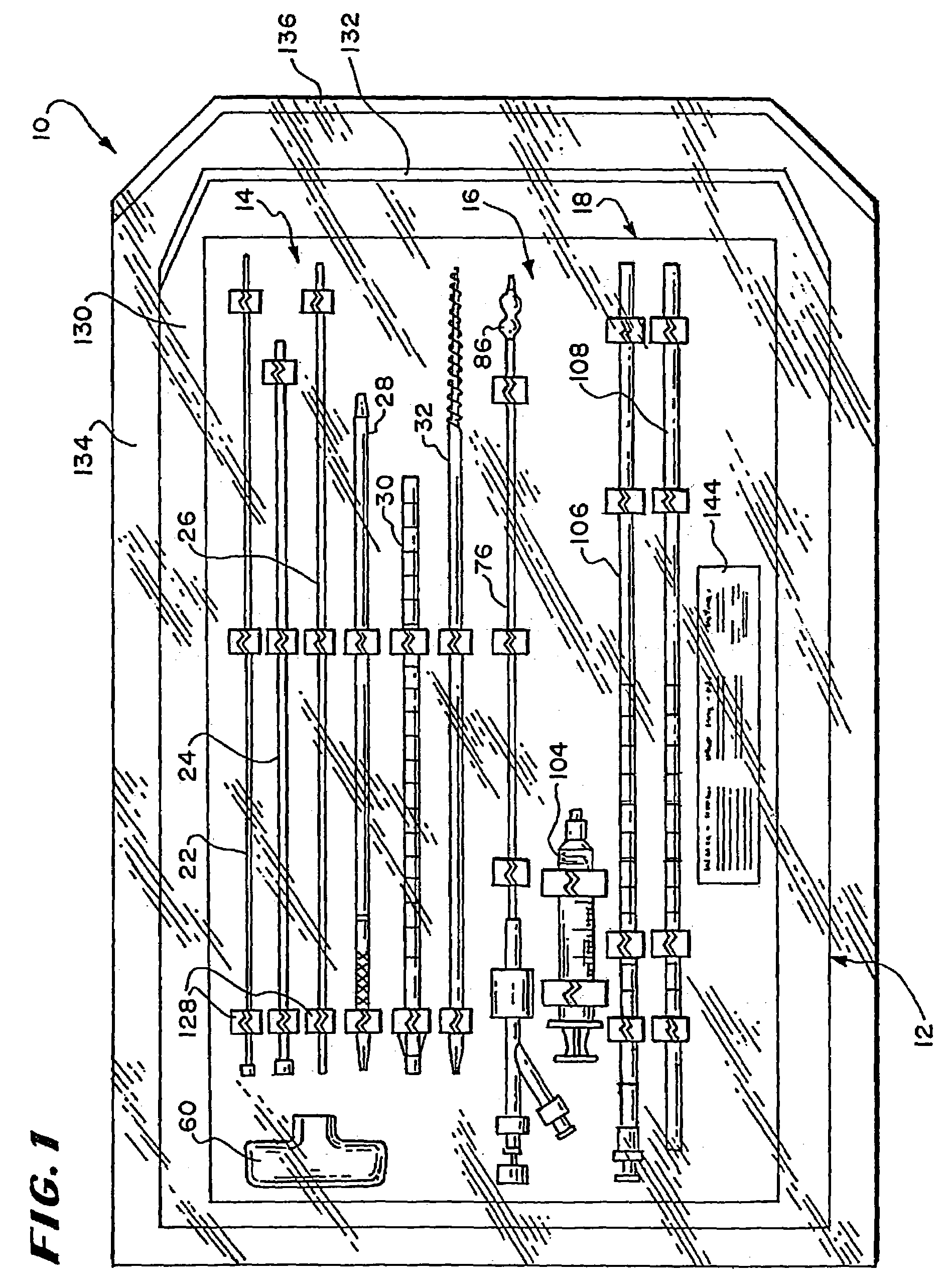
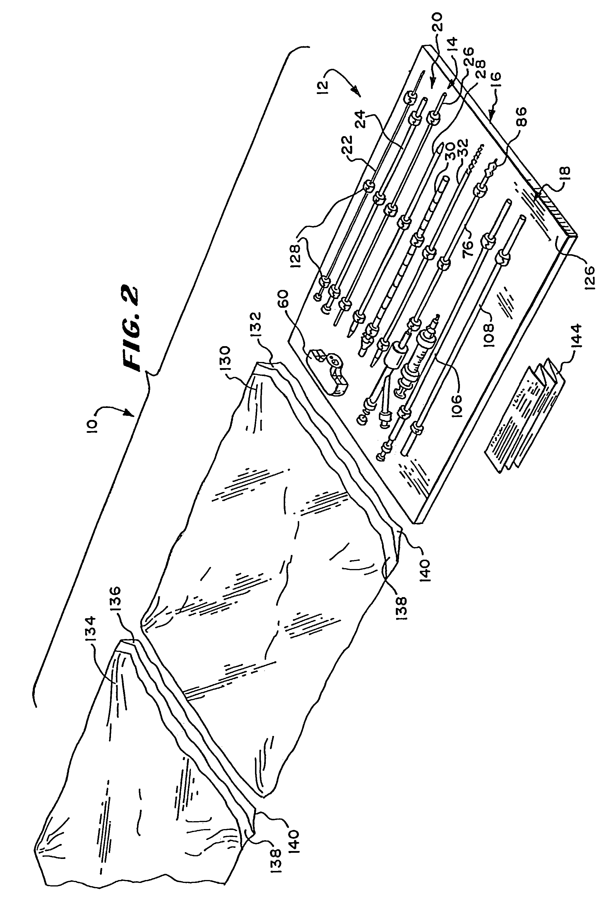
[0061]FIGS. 1 and 2 show a system 10 of functional instruments. In use, certain instruments of the system 10 are deployed in a purposeful manner to penetrate tissue and gain subcutaneous access to the inside of a bone. Inside bone, other instruments of the system 10 are deployed to form a cavity in cancellous bone, into which a material is placed for therapeutic purposes.

[0062]In the illustrated embodiment, the system 10 is arranged as a prepackage kit 12 in three functional instrument groups 14, 16, and 18. The first group 14 (which FIG. 3 shows outside the kit 12) comprises instruments whose purp...


PUM


Abstract

Systems and methods for delivering material into bone deploy a cannula through soft tissue to establish a subcutaneous path into bone. A material is introduced into bone through the cannula. The systems and methods advance a tamping instrument through the cannula to urge material residing in the cannula into bone. The introducing step delivers material at a pressure no greater than about 360 psi.

Description

RELATED APPLICATIONS[0001]This application is a divisional of application Ser. No. 09 / 804,107, filed Mar. 12, 2001 now U.S. Pat. No. 6,613,054, which is a divisional of application Ser. No. 09 / 134,323, filed Aug. 14, 1998, now U.S. Pat. No. 6,241,734 issued Jun. 5, 2001.FIELD OF THE INVENTION[0002]The invention generally relates to the treatment of bone conditions in humans and other animals.BACKGROUND OF THE INVENTION[0003]Injection devices similar to a household caulking gun are used to inject bone cement into bone. A typical bone cement injection device has a pistol-shaped body, which supports a cartridge containing bone cement. A trigger actuates a spring-loaded ram, which forces a volume of bone cement in a viscous condition through a suitable nozzle and into the interior of a bone targeted for treatment. According to the teachings of U.S. Pat. Nos. 4,969,888 and 5,108,404, a cavity can be first formed by compacting cancellous bone inside the bone, into which the bone cement is...

Claims


Application Information

Patent Timeline
Patent Type & Authority Patents(United States)
IPC IPC(8): A61B17/58A61F2/00A61B17/56A61B17/00A61B17/16A61B17/34A61B17/88A61B19/00A61B19/02A61F2/28A61F2/44A61F2/46A61F2/958A61M37/00
CPCA61B17/8816A61B17/8822A61B17/8833A61B17/8855A61F2/4601A61B17/1671A61B17/3472A61B17/7097A61B17/8805A61B19/0271A61B19/54A61B2017/00261A61B2017/00464A61B2017/00867A61B2019/0219A61B2019/462A61F2/44A61F2002/2835A61F2002/3008A61F2002/4602A61F2002/4624A61F2002/4662A61F2250/0098A61F2310/00353A61B2050/0065A61B50/33A61B2090/062A61B90/39A61F2/4603
Inventor SCRIBNER, ROBERT MREO, MICHAEL LREILEY, MARK ABOUCHER, RYAN
Owner ORTHOPHOENIX
Learn More