
Eccentric planetary traction drive transmission with flexible roller for adaptive self-loading mechanism

Active Publication Date: 2006-12-26
THE TIMKEN CO
View PDF18 Cites 13 Cited by
  • Summary
  • Abstract
  • Description
  • Claims
  • Application Information

AI Technical Summary

Benefits of technology

[0016]This patent application relates to planetary traction drives in general and specifically to an eccentric, cylindrical planetary traction drive having at least one flexible planetary roller capable of providing adaptive self-loading mechanism to facilitate the transfer of rotational motion and torque. The current invention also provides a traction drive that allows for an adaptive torque responsive loading and also provides a traction drive with well-balanced contact stresses at the most critical contacts.

Problems solved by technology

The spin motion not only offsets the high-efficiency otherwise provided by the traction drive, but also causes component wear and high break away torque.
Although this design offers torque actuated loading mechanism and greater torque capability, it is somewhat complex in construction.
However, generating sufficient normal force at the contacts has been a challenge.
The pre-load generated by such means, in general, can not be adjusted during operation.
For partial load application, traction drives are unnecessarily overloaded.
This has negative impacts on transmission efficiency and service life.
Such a loading mechanism was either over conservative or inadequate when the maximum available traction coefficient changes with contact load.
In most of the prior art designs, this has led to different contact stresses at the contact between the sun roller and planets.
This could cause a change in eccentricity between input and out put shafts as the loading roller adjust their positions.

Method used


Image

  • Eccentric planetary traction drive transmission with flexible roller for adaptive self-loading mechanism
  • Eccentric planetary traction drive transmission with flexible roller for adaptive self-loading mechanism
  • Eccentric planetary traction drive transmission with flexible roller for adaptive self-loading mechanism

Examples


Embodiment Construction

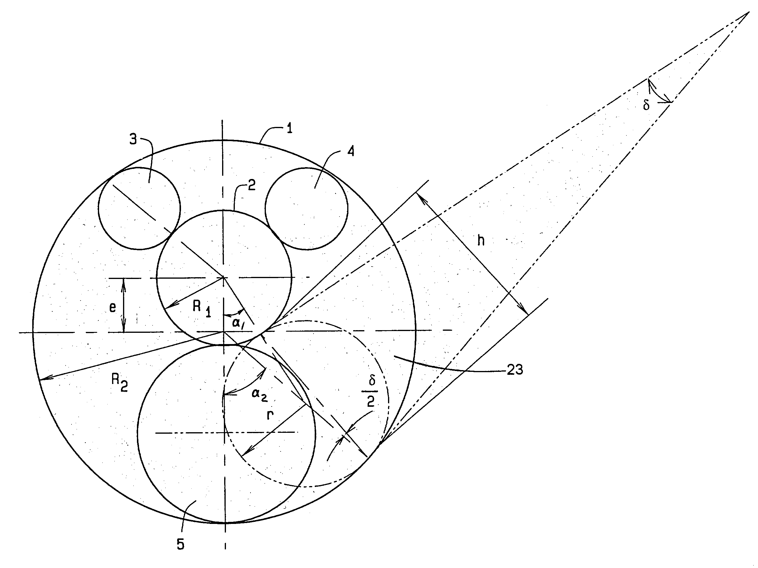
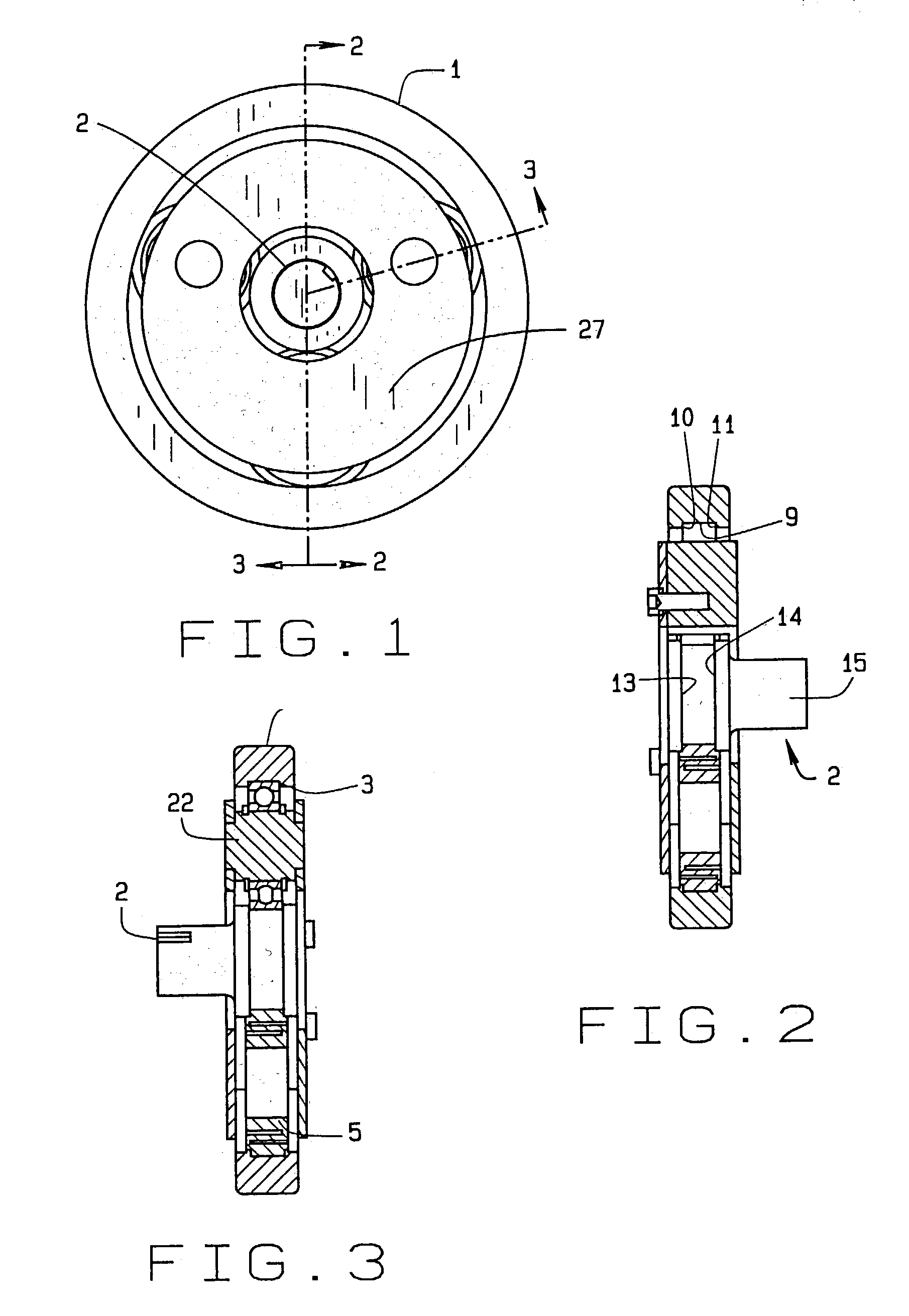
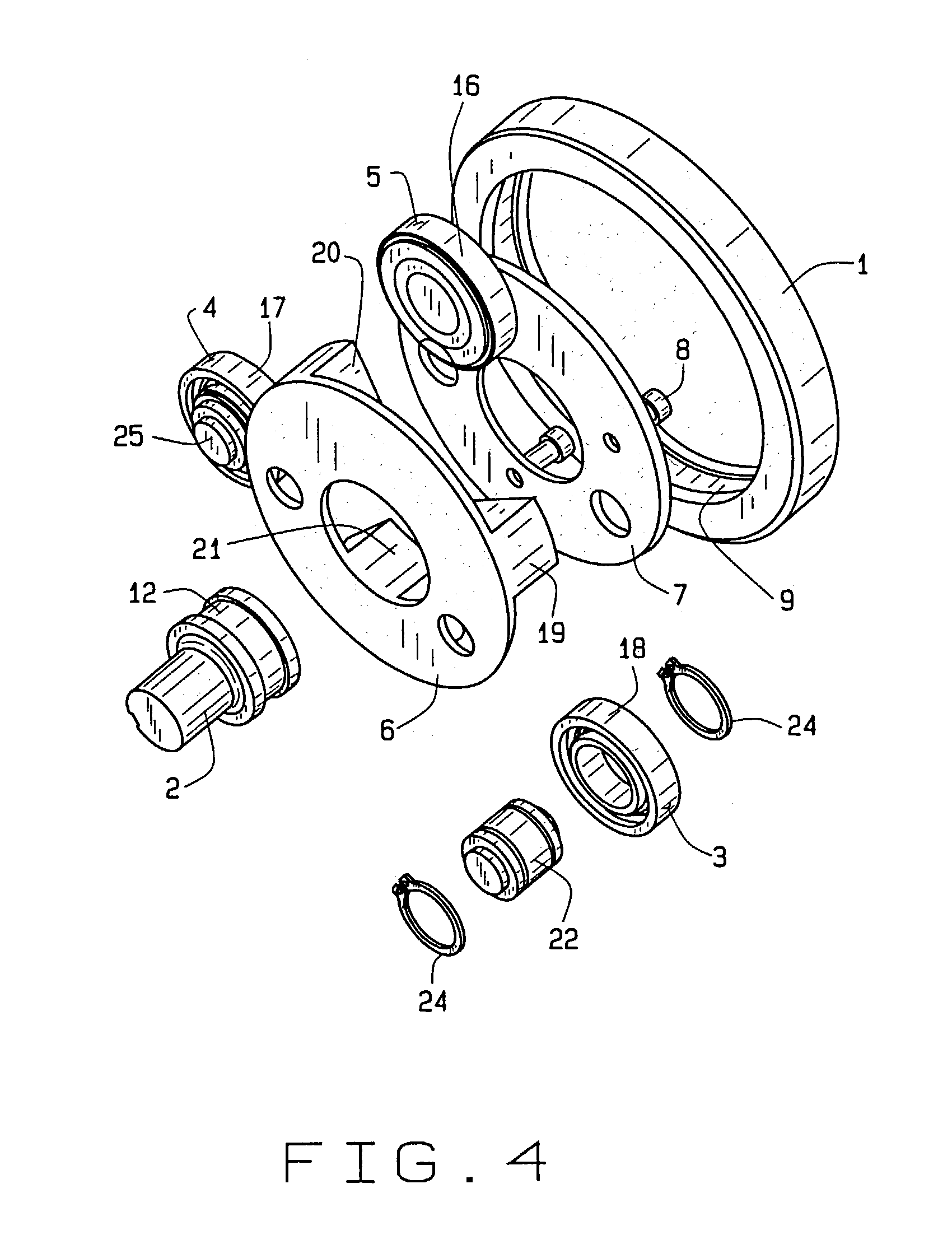
[0026]Referring now to FIGS. 1 and 2, one embodiment of the cylindrical planetary traction drive A comprises an outer ring member 1, a sun roller member 2, a first planetary roller 5, two second planetary rollers 3&4, and a carrier member 27. The outer ring member 1 further comprises a first cylindrical raceway 9 surrounding the axis of rotation, and a first fixed flange 10 and a second fixed flange 11.

[0027]The sun member 2 includes a second cylindrical raceway 12, a third fixed flange 13, a fourth fixed flange 14, and a shaft 15. The first planetary roller 5 has a third cylindrical raceway 16, and the second planetary rollers 3 and 4 have a fourth cylindrical raceway 18 and 17 respectively. The first planetary roller 5 and the two second planetary rollers 3 and 4 are placed between and in contact with first cylindrical raceway 9 and second cylindrical raceway 12.

[0028]At least one of either the planetary roller 5 or the planetary rollers 3 and 4 is flexible compared to other rolle...


PUM


Abstract

An eccentric planetary traction drive transmission which includes at least two planetary rollers, sun roller member, and a carrier member. One of the planetary rollers is flexible and is positioned between and in contact with an outer ring member and the sun roller member. Rotation of either the outer ring member or the sun roller member wedges the flexible planetary roller within a convergent wedge gap which squeezes the flexible planetary roller between the outer ring member and the sun roll member. Friction between the flexible planetary roller, the sun roller member, and the outer ring member transmits rotational motion and torque between the outer ring member and the sun roller member. The other at least one supporting planetary roller is a supporting roller which supports the sun roller member and the carrier member. A plurality of bearings supports the sun roller member within the outer ring member and the at least one supporting planetary roller.

Description

CROSS-REFERENCE TO RELATED APPLICATIONS[0001]This application is related to U.S. Provisional Patent Application 60 / 354,010 filed Jan. 31, 2002, and U.S. Provisional Patent Application No. 60 / 734,746 filed Apr. 23, 2002, from which priority to both applications is claimed.STATEMENT REGARDING FEDERALLY SPONSORED RESEARCH OR DEVELOPMENT[0002]Not applicable.BACKGROUND OF THE INVENTION[0003]1. Field of the Invention[0004]This invention relates in general to a planetary traction drive transmission, and, more particularly, to a planetary traction drive transmission with at least one flexible roller having an adaptive self-loading mechanism.[0005]2. Description of Related Art[0006]Traction drives use frictional force to transmit torque and power. Because the power is transmitted between two smooth surfaces, often through a thin layer of lubricant, a traction drive possesses unique characteristics that are not readily attainable by gear drives. These characteristics include quietness, high-e...

Claims


Application Information

Patent Timeline
IPC IPC(8): F16H1/32F16H13/08F16H13/14
CPCF16H13/06F16H13/14
Inventor AI, XIAOLAN
Owner THE TIMKEN CO
Learn More