Air bag system

a technology of air bags and air bags, which is applied in the direction of pedestrian/occupant safety arrangements, vehicular safety arrangements, vehicle components, etc., can solve the problems of increased processing costs, difficult to control the deployment shape of air bags as desired, so as to achieve freer control of the deployment shape and simple construction

Inactive Publication Date: 2006-12-26
HONDA MOTOR CO LTD
View PDF10 Cites 9 Cited by
  • Summary
  • Abstract
  • Description
  • Claims
  • Application Information

AI Technical Summary

Benefits of technology

[0004]The invention is made to address these situations, and an object thereof is to enable a freer control of the deployment shape of the air bag with a simple construction.
[0006]According to the construction that is described above, since the external strap which is passed through the through hole which passes through the air bag in the tunnel-like fashion to open in the side surfaces of the air bag is disposed on the outer circumference of the air bag, the deployment shape of the air bag can be controlled by the external strap so as to enhance the occupant restraining performance of the air bag effectively. In particular, by disposing the external strap on the external portion of the air bag, not only can the number of man-hours for processing be reduced when compared with a case where the strap is disposed in the interior of the air bag but also the deployment shape of the air bag can be controlled more freely due to the external strap being brought into not a point contact but a line or surface contact with the air bag, and moreover, the behaviors of the air bag in the deployment process can be stabilized.

Problems solved by technology

While an air bag which deploys into the passenger compartment of a vehicle to restrain an occupant at the time of collision of the vehicle is farmed by sewing a plurality of base fabrics, it is difficult to control the deployment shape of the air bag as desired only by devising the shapes of the base fabrics.
However, since a job of installing the strap in the interior of the air bag is troublesome, the processing costs are increased, and since the tension of the strap is applied only to the connecting portion with the base fabric, it is difficult to control the deployment shape of the air bag as desired.

Method used


Image

  • Air bag system
  • Air bag system
  • Air bag system

Examples


Embodiment Construction

[0017]Modes for carrying out the invention will be described below based on embodiments of the invention illustrated in the accompanying drawings.

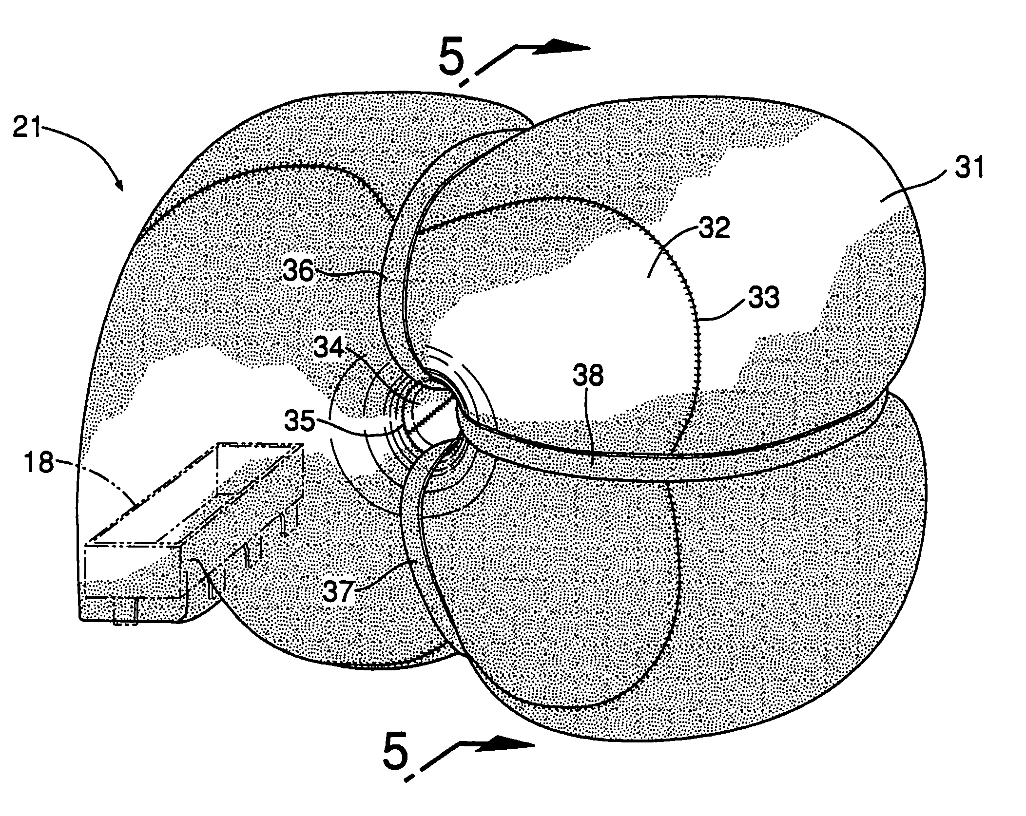
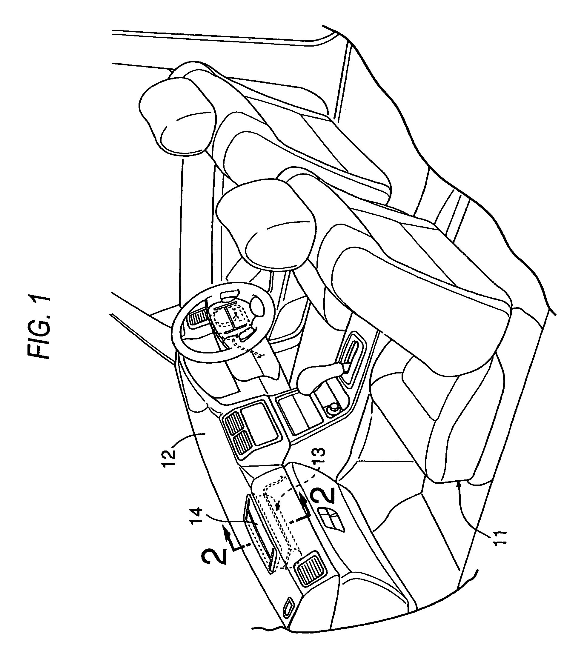
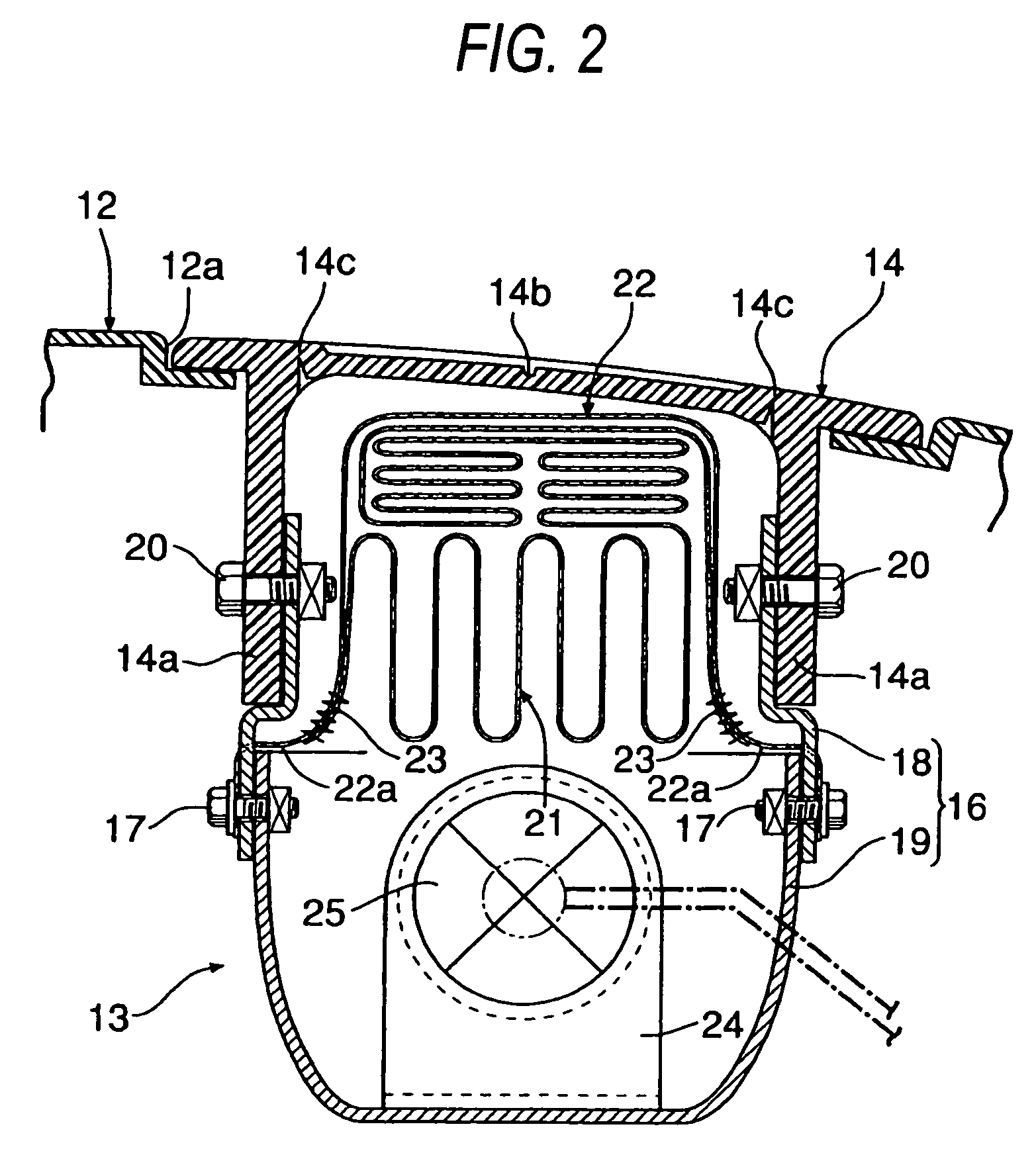
[0018]FIGS. 1 to 6 illustrate a first embodiment of the invention, in which FIG. 1 is a perspective view of a front part of a passenger compartment of an automobile, FIG. 2 is an enlarged cross-sectional view taken along the line 2—2 in FIG. 1, FIG. 3 is an exploded perspective view of an air bag system, FIG. 4 is a perspective view of an air bag in a deployed state, FIG. 5 is a cross-sectional view taken along the line 5—5 in FIG. 4, and FIG. 6 is an exploded perspective view of the air bag.

[0019]As shown in FIG. 1, an air bag system 13 for a front passenger seat 11 is provided at an upper portion in a dashboard 12 disposed in front of the front passenger seat 11.

[0020]As shown in FIGS. 2 and 3, a retainer 16 forte air bag system 13 is fixed to support portions 14a which extend downwardly from a lid 14 fixed to the sides of an opening for...


PUM


Abstract

By disposing external straps 36 to 38 which are passed through a tubular member 34 which passes through an air bag 21 in a tunnel-like fashion to open in side surfaces of the air bag 21 are disposed on an outer circumference of the air bag 21 and controlling the deployment shape of the air bag 21 by the external straps 36 to 38 so disposed, the occupant restraining performance of the air bag can effectively be enhanced.

Description

BACKGROUND OF THE INVENTION[0001]The present invention relates to an air bag system in which a folded air bag and an inflator are supported on a retainer, so that the air bag is inflated to be deployed into a passenger compartment of a vehicle by a gas produced by the inflator at the time of collision.[0002]While an air bag which deploys into the passenger compartment of a vehicle to restrain an occupant at the time of collision of the vehicle is farmed by sewing a plurality of base fabrics, it is difficult to control the deployment shape of the air bag as desired only by devising the shapes of the base fabrics. To cope with this, conventionally, a strap for connecting the base fabrics together or a strap for connecting the base fabric to a retainer is provided in the interior of the air bag, whereby the deployment shape of the air bag is controlled by allowing the tension of the strap to be applied to the base fabrics at the time of deployment of the air bag (for example, refer to ...

Claims


Application Information

Patent Timeline
Patent Type & Authority Patents(United States)
IPC IPC(8): B60R21/231B60R21/16B60R21/233B60R21/2338
CPCB60R21/231B60R21/2338B60R21/205B60R2021/23386
Inventor KAI, TAKESHI
Owner HONDA MOTOR CO LTD
Why Eureka
Try Eureka