
Land grid array socket having improved terminals

a technology of terminals and grid arrays, applied in the direction of coupling contact members, coupling device connections, electrical apparatus construction details, etc., can solve the problems of low terminal capacitance, inability to meet the requirement of high frequency transmission, and relatively high impedance of the whole terminal, etc., to achieve short circuit paths, low impedance, and high frequency

Inactive Publication Date: 2006-12-19
HON HAI PRECISION IND CO LTD
View PDF4 Cites 18 Cited by
  • Summary
  • Abstract
  • Description
  • Claims
  • Application Information

AI Technical Summary

Benefits of technology

This design ensures effective high frequency signal transmission by minimizing impedance and optimizing capacitance, addressing the limitations of conventional terminals.

Problems solved by technology

However, capacitance of the terminal 7 is relatively low which cannot satisfy the requirement of high frequency transmission.
The long circuit path still leads to a relatively high impedance of the whole terminal 8, which is not desirable in high frequency transmission.

Method used


Image

  • Land grid array socket having improved terminals
  • Land grid array socket having improved terminals
  • Land grid array socket having improved terminals

Examples


Embodiment Construction

[0016]Reference will now be made to the drawings to describe the present invention in detail.

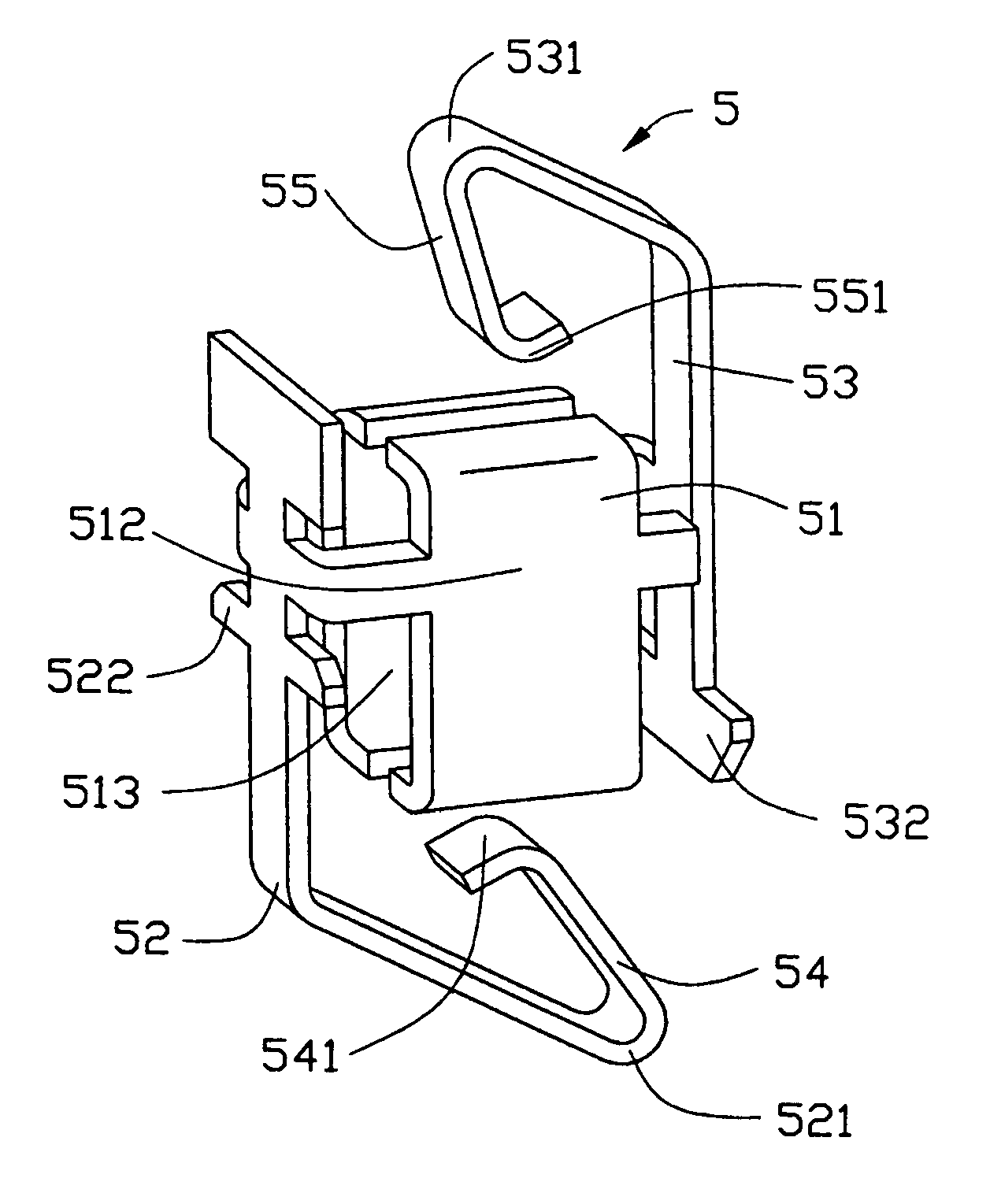
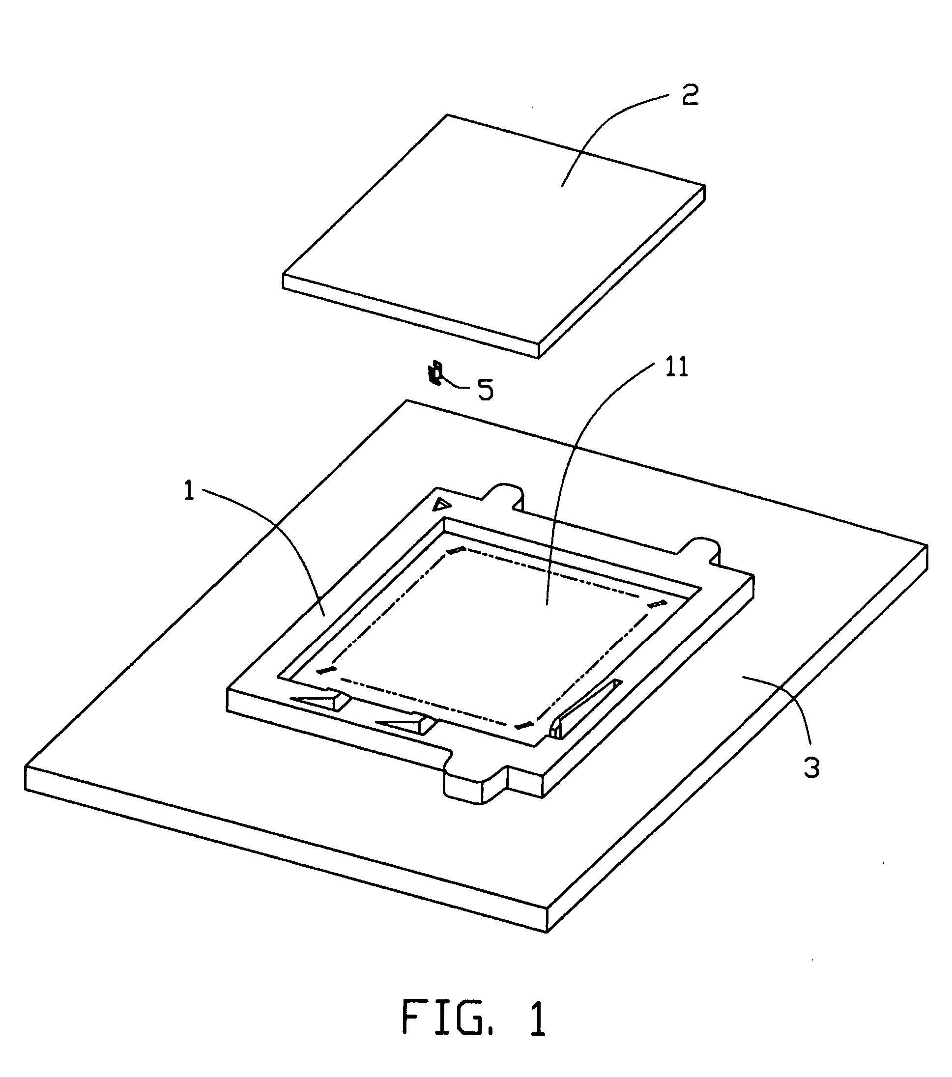
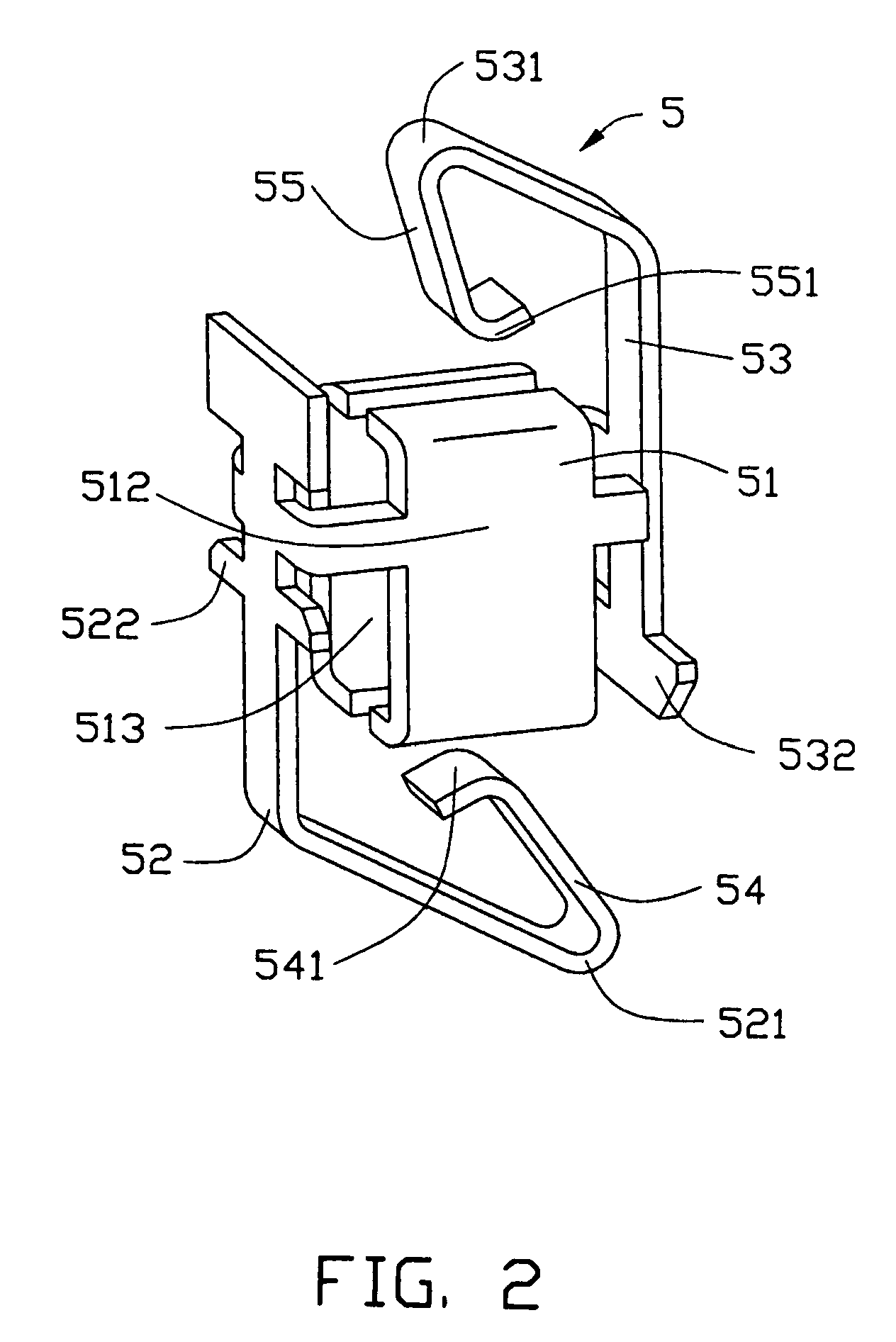
[0017]Referring to FIGS. 1 and 3, a land grid array socket 1 in accordance with a preferred embodiment of the present invention is illustrated. The socket 1 includes a planar and rectangular housing 11, the housing 11 is made of insulative material such as plastic, and a plurality of passageways 113 extend throughout a top surface 111 and a bottom surface 112 of the housing 11. The socket 1 is sandwiched between a first electronic component 2 and a second electronic component 3 and electrically and mechanically interconnects the first and the second components 2 and 3 via a number of electrical terminals 5 received in the passageways 113.

[0018]In this embodiment, the first electronic component 2 might be an IC chip having a plurality of electrical pads formed at a bottom surface thereof and the second electronic component 3 might be a motherboard having a plurality of electrical pads formed ...


PUM


Abstract

A land grid array socket (1) comprises an insulative housing (11) having a plurality of passageways (113) extending throughout a top surface (111) and an opposite bottom surface (113) and a plurality of electrical terminals (5) received in corresponding passageways, respectively. Each terminal including a base portion (51) in the passageway and a first spring arm (55) extending out of the top surface of the housing and adapted to be electrically connected with a first electronic component (2) and a second spring arm (54) extending out of the bottom surface of the housing and adapted to be electrically connected with a second electronic component (3). Wherein the first and the second spring arms each has a resisting portion (531, 521), the resisting portions resist the base portion when the spring arms are pressed by the first and the second electronic components so as to form a shorter electrical circuit path between the electronic components.

Description

BACKGROUND OF THE INVENTION[0001]1. Field of the Invention[0002]The present invention relates to the art of electrical connectors, and more particularly to a land grid array (LGA) socket having electrical terminals for electrically connecting two separate electronic components.[0003]2. The Prior Art[0004]A conventional terminal 7 of a land grid array (LGA) socket is illustrated in FIG. 6. The terminal 7 includes a base portion for securing the terminal 62 in an insulative housing of the LGA socket and a pair of spring arms 72 and 73 respectively extending out of opposite surfaces of the housing for resisting two separate electronic components so as to establish electrical connection between the two components. However, capacitance of the terminal 7 is relatively low which cannot satisfy the requirement of high frequency transmission. Further, an electrical circuit path of the terminal 7 is from a top contacting point 721 of the spring arm 72 to a bottom contacting point 731 of the s...

Claims


Application Information

Patent Timeline
Patent Type & Authority Patents(United States)
IPC IPC(8): H01R12/00H01R13/24H05K7/10
CPCH01R13/2435H01R12/7076H01R12/714H05K7/1069
Inventor LEE, GENN-SHENGCHEN, LI-CHENHUANG, YAO-CHI
Owner HON HAI PRECISION IND CO LTD
Learn More