Support apparatus

a support apparatus and support technology, applied in the direction of machine supports, building scaffolds, manufacturing tools, etc., can solve the problems of avoiding the difficulty of achieving coplanar work supports, and achieve the effect of convenient adjustment, high portability, and elimination of the possibility of splintering

Active Publication Date: 2006-12-12
COLGROVE MARK R
View PDF4 Cites 8 Cited by
  • Summary
  • Abstract
  • Description
  • Claims
  • Application Information

AI Technical Summary

Benefits of technology

[0011]The support apparatus of the present invention provides many advantageous features for a variety of purposes. The apparatus has a width that may be easily adjusted to virtually any magnitude desired by a fabricator to create an upper work region for accommodating workpieces having many different shapes and sizes. The improved upper work region has multiple elevated support elements which may be positioned as needed to provide open spaces therebetween. The open spaces assist in cutting and drilling processes without any hindrances whatever. In a preferred embodiment, at least two integral support elements may be used in combination with a plurality of additional support elements. In accord with an important feature of the invention, all support elements may advantageously be coplanar. The additional coplanar support elements are particularly useful for supporting larger workpieces for cutting and drilling and may fully support large workpieces on both sides of a cut during a cutting operation. The possibility of splintering is eliminated. Each support apparatus preferably includes two support frames, and extra support frames may be interconnected therewith to form support configurations having additional shapes and sizes. Importantly, the additional configurations may also have coplanar work surfaces. The support apparatus of the present invention is highly portable, and it may be erected and broken down without the use of tools. It may be erected to form a rugged and stable yet open work surface which may be easily expanded, and it may be broken down into a compact unit. It may be manufactured with excellent economy.
[0012]In accordance with a preferred embodiment of the present invention, two specially configured support frames are rigidly connected to each other by means of two horizontal linking members. The horizontal linking members may be beams of lumber having common cross-sectional dimensions, and virtually any lengths thereof may be used in order to provide the desired spacing between the frames. Moreover, because the linking members have common cross-sectional dimensions, additional linking members with different lengths may be easily obtained from virtually any lumber retailer. The frames may be spaced apart by any distance up to the lengths of the linking members for providing the desired width for the upper work region. Specially configured engagement means have been developed for fastening the linking members to the support frames. In a preferred embodiment of the invention, placing a load upon the apparatus tightens the connections between the linking members and the support frames by creating “gripping” force couples. When present, such force couples restrict all movement of the linking members relative to the support frames, including rotation and translation (e.g., shifting within the engagement means). The present configuration results in a very stable and safe construction. Furthermore, when the apparatus is not loaded, the “gripping” couple is minimal and a user may conveniently remove the linking members from the support frames.
[0013]Each support frame preferably has at least one integral support element having an upper surface above those of the linking members for supporting a workpiece or the like thereon. The support frames and linking members together form an upper frame with an open upper work region, wherein the top surfaces of the integral support elements are coplanar with each other in an upper plane and the top surfaces of the linking members are coplanar with each other in a lower plane. To particular advantage, additional support elements which are typically unattached may be easily positioned upon the linking members. The additional support elements are sized and shaped so that their upper surfaces are coplanar with the upper surfaces of the integral support elements. The additional support elements may be moved easily from one position to another along the lengths of the linking members while remaining coplanar with each other and with the integral support elements.
[0014]The foregoing configuration advantageously provides a plurality of easily movable support elements with upper support surfaces that are coplanar. Using the apparatus is therefore similar to using a plurality of sawhorses, yet obviates the difficulty of achieving coplanar work supports. Specifically, all the support elements of the present invention are held in a single upper plane with open spaces therebetween. In addition, the support elements are more easily and more rapidly movable than multiple sawhorses would be. In accordance with a preferred embodiment of the invention and because of the linked configuration, the erected support apparatus is particularly stable and may also be easily transported as a single unit rather than as multiple separate sawhorses, providing increased convenience on a jobsite. The apparatus also may be conveniently transported together with any workpieces thereon, eliminating the need to remove the workpieces, transport each sawhorse individually, and then transport and replace the workpieces.
[0015]In a particularly preferred embodiment of the present invention, each support frame is a rigid structure consisting of two top rails, two bottom rails, and two legs. Each of the four rails is attached to both legs, increasing the rigidity of the frame. Engagement means to hold the linking members securely in place may be provided by the top and bottom rails. The linking members preferably have rectangular cross sections, whereby each linking member may be inserted easily between the top and bottom rails for a tight fit. Once a linking member is inserted and the apparatus is loaded, the two top and two bottom rails grip the linking member securely therebetween by applying a “gripping” couple thereto. The engagement means therefore restricts an attached linking member from moving with respect to the rails (as well as to the respective frame) when the apparatus is loaded.
[0016]The two top rails further provide integral support elements for supporting a workpiece or the like thereon. The entire upper surfaces of two (or more) interconnected frames, including the “dual” upper surfaces of the top rails and the upper surfaces of the legs, provide ample surface area to support many types and sizes of workpieces. Because the upper surfaces of the frames are higher than the upper surfaces of the linking members, a completely open region is provided between the frames. Therefore, e.g., a fabricator may cut a workpiece with a circular saw across the entire depth of the apparatus, without cutting through the linking members or any other obstacles below the workpiece. In accordance with the present embodiment, the configuration of the rails permits the apparatus to be erected and broken down with ease and without tools. One frame may conveniently be nested with the other such that the legs of one frame are inserted between the rails of the other frame to provide a compact and lightweight unit. Short linking members, as well as additional support elements, may also be inserted between the rails of both nested units, providing a highly portable unit.

Problems solved by technology

Using the apparatus is therefore similar to using a plurality of sawhorses, yet obviates the difficulty of achieving coplanar work supports.

Method used


Image

  • Support apparatus
  • Support apparatus
  • Support apparatus

Examples


Embodiment Construction

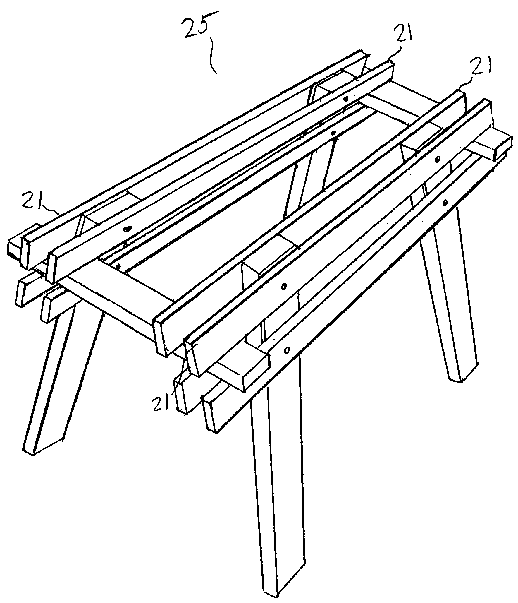
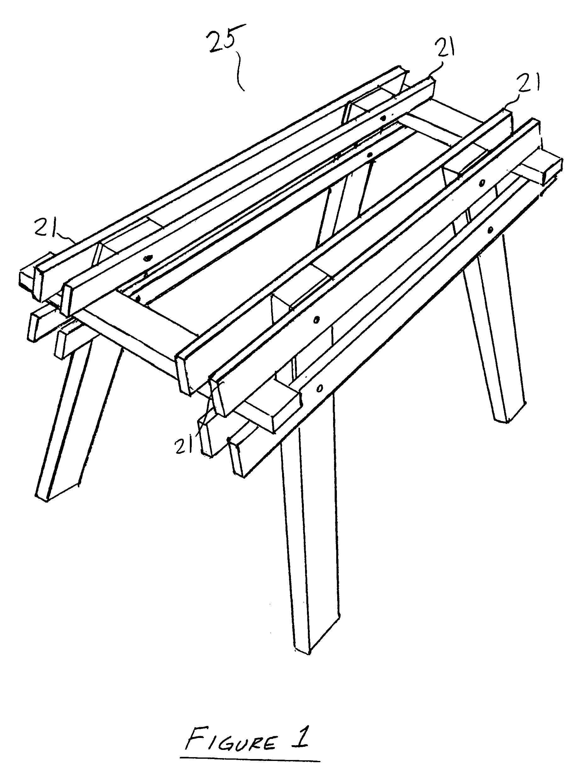
[0040]In accordance with a preferred embodiment of the present invention; an improved support apparatus is provided. The apparatus is preferably modular, providing a structure that a user may easily assemble at a jobsite and may easily break down into a compact unit for convenient transport and storage. It may include few parts for fast assembly as well as economical manufacture. The apparatus may include an upper frame with an open upper work region to assist in such operations as cutting, drilling, and the like. To particular advantage, a plurality of support elements may be provided to form a planar upper work surface which provides ample support to larger workpieces. The apparatus is versatile and may be used for a large variety of purposes and to form a large variety of structural configurations.

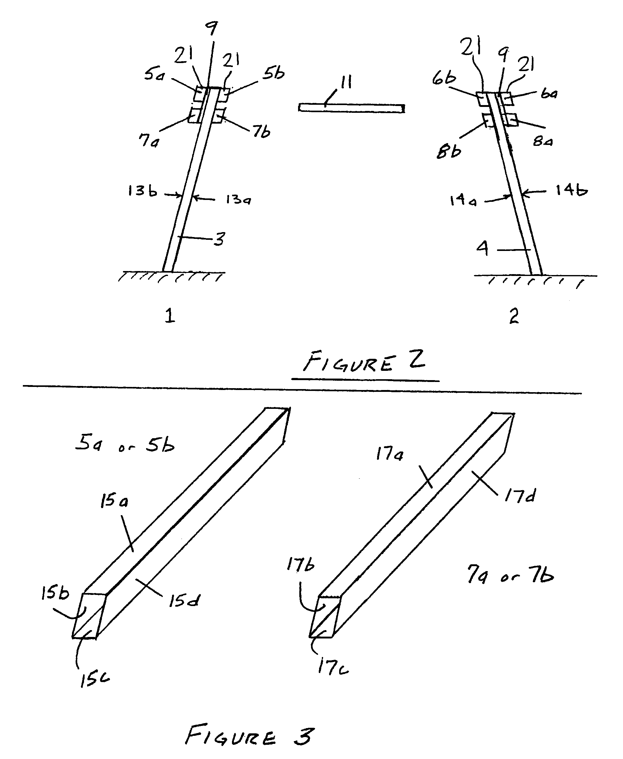
[0041]As shown in FIGS. 1–3, a preferred embodiment of the support apparatus of the invention, referred to generally by the reference numeral 25, includes a first support frame (1) and ...


PUM


Abstract

An improved support apparatus for use in many manufacturing operations. The improved apparatus may be used as a workbench having an open upper region to assist in such operations as drilling and cutting. The apparatus can accommodate a large variety of sizes and shapes of workpieces and comprises a highly portable unit.

Description

RELATED APPLICATION[0001]This application claims the priority of U.S. Provisional Application No. 60 / 458,534, filed Mar. 31, 2003, the contents of which are incorporated by reference.FIELD OF THE INVENTION[0002]The present invention relates generally to a versatile support apparatus. More specifically, the invention relates to an improved portable workbench having an upper frame and coplanar support elements to create an open upper work region for assisting in many manufacturing processes.BACKGROUND OF THE INVENTION[0003]A variety of support structures for assisting in manufacturing and fabrication operations are known. A simple worktable with a rigid support framework and a solid upper surface is common. Several worktable configurations are available for use in such processes as assembly, grinding, welding, and the like. However, other processes such as drilling and cutting (e.g., cutting with a circular saw) are more easily performed on a support structure having a support surface...

Claims


Application Information

Patent Timeline
Patent Type & Authority Patents(United States)
IPC IPC(8): E04G1/34
CPCB25H1/06B25H3/06
Inventor COLGROVE, MARK R.
Owner COLGROVE MARK R
Why Eureka
Try Eureka