
Compensation system and method for negative capacitive coupling in IDC

a capacitive coupling and negative technology, applied in the field of communication connectors, can solve the problems of affecting the compliance of sophisticated communication standards, affecting the performance of communication devices, and affecting the ability of high-speed communication devices such as computers to achieve the effect of reducing crosstalk

Active Publication Date: 2006-11-28
LEVITON MFG
View PDF46 Cites 66 Cited by
  • Summary
  • Abstract
  • Description
  • Claims
  • Application Information

AI Technical Summary

Benefits of technology

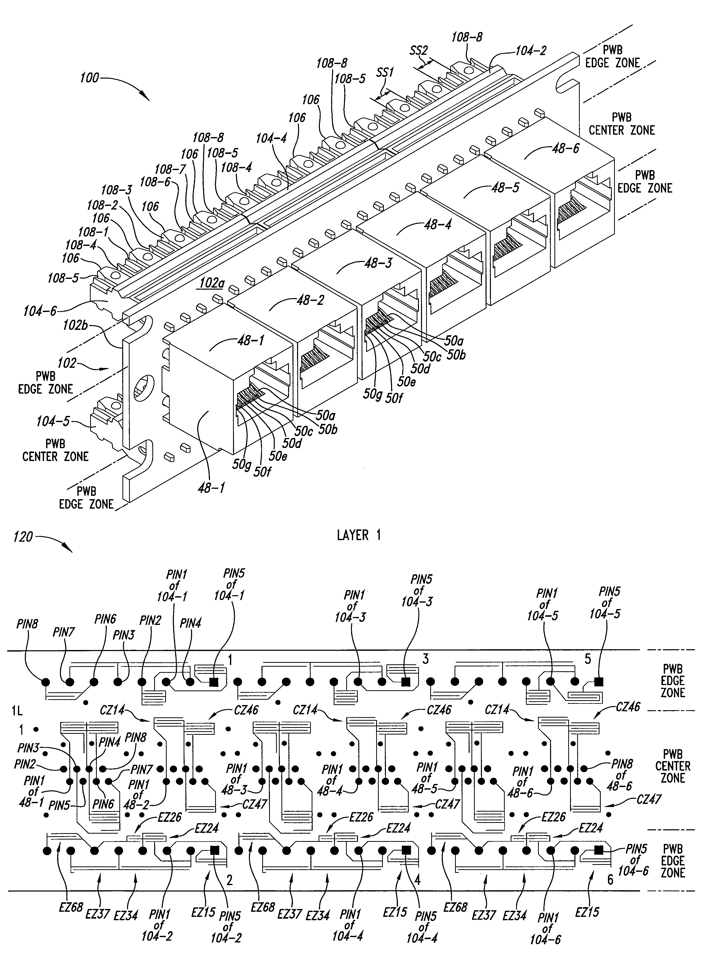
[0010]A circuit board has a plurality of jack pads, a plurality of IDC pads, and a plurality of internal conductors. Each of the plurality of jack pads are electrically coupled to a different one of the plurality of jack contact members so that a first tip jack pad, a first ring jack pad, a second tip jack pad, and a second ring jack pad are electrically coupled to the first tip jack contact member, the first ring jack contact member, the second tip jack contact member, and the second ring jack contact member, respectively. Each of the plurality of IDC pads are electrically coupled to a different one of the plurality of IDC elements. Each of the plurality of internal conductors are electrically coupled to a different one of the plurality of jack pads and a different one of the plurality of IDC pads. The circuit board has a first interdigitated capacitance electrically coupled to the first tip IDC element and electrically coupled to the second tip IDC element and has a second interdigitated capacitance electrically coupled to the first ring IDC element and electrically coupled to the second ring IDC element. The first interdigitated capacitance and the second interdigitated capacitance is sized to reduce crosstalk associated with the first capacitance.

Problems solved by technology

The use of communication connectors with telephones does not result in the degradation of signal quality because telephones typically have limited bandwidth.
However, high-speed communication devices, such as computers, can suffer significant degradation of signal quality due to conditions such as crosstalk occurring where a signal on a line pair interferes with a signal on another line pair.
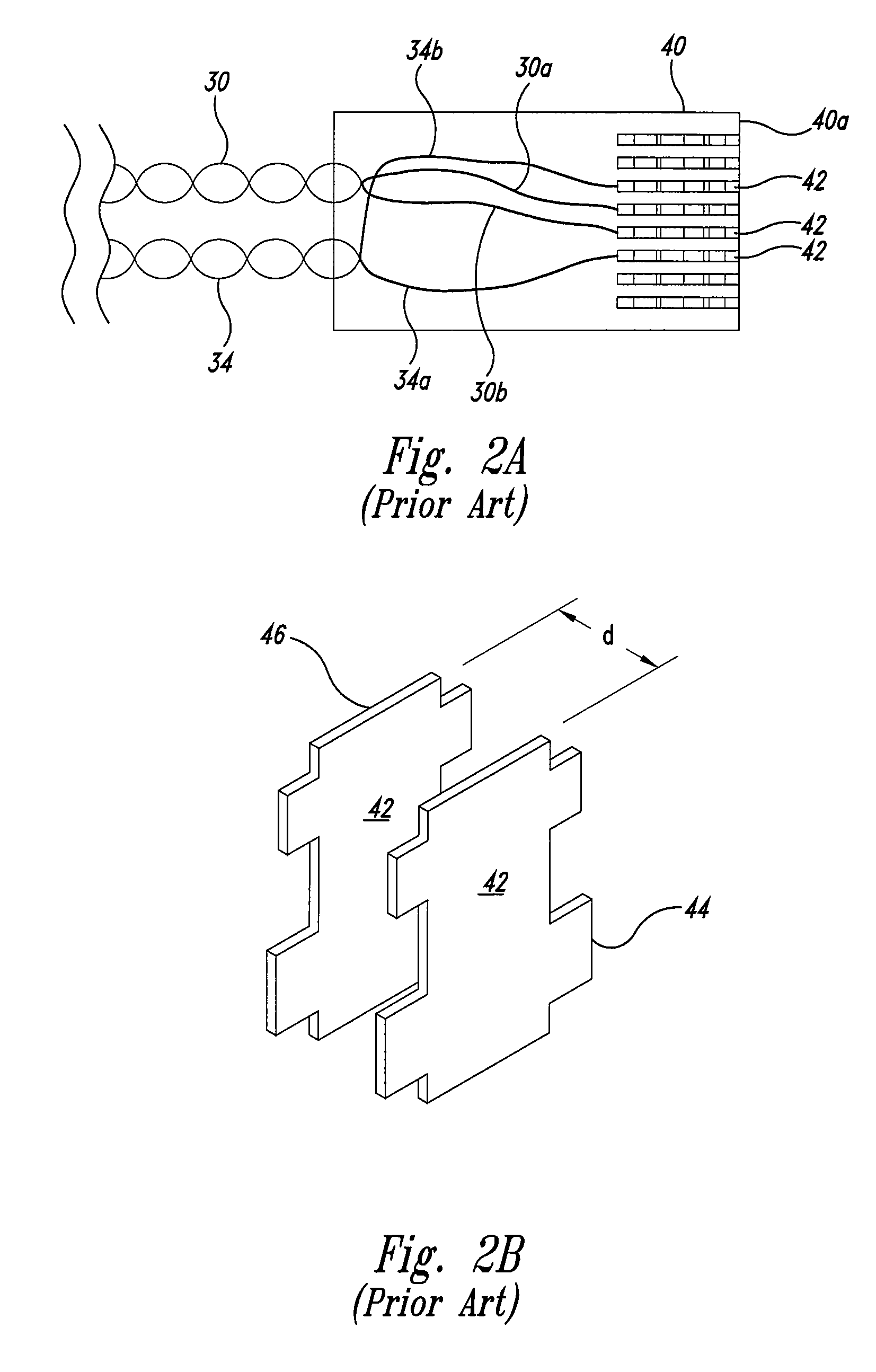
Conventional insulation displacement connector (IDC) designs have associated capacitive and inductive crosstalk that hinders efforts to comply with sophisticated communication standards.
Having different IDC configurations can be undesirable, however, since other problems can be introduced including those involved with equipment logistics and support.

Method used


Image

  • Compensation system and method for negative capacitive coupling in IDC
  • Compensation system and method for negative capacitive coupling in IDC
  • Compensation system and method for negative capacitive coupling in IDC

Examples


Embodiment Construction

[0027]A patch panel with crosstalk reduction system and method is described herein to meet category 6 requirements while allowing for physical connector configurations that are compatible with other standards such as category 5 and category 5e. The development of a category 6 component compliant patch panel per TIA-568-B.2-1 standards for near-end crosstalk (NEXT) includes addressing crosstalk created in the associated RJ-45 plug and applying cancellation techniques in a jack position of a patch panel module so that the NEXT of the connector satisfies the specification. Conventional IDCs introduce a certain amount of crosstalk that must be dealt with in addition to the crosstalk created in the RJ-45 plug. Conventional category 6 designs reduce the impact of the IDC by changing the IDC to a non-standard configuration. For instance, in some conventional approaches, the spacing between pairs of IDC contacts are increased, which minimizes the capacitive crosstalk. In these approaches, t...


PUM


Abstract

A insulation displacement connector (IDC) patch panel includes a circuit (PC) board with interdigitated capacitance for balancing out inherent capacitance found within IDCs of the panel. Unwanted cross-talk signals are reduced as a consequence.

Description

BACKGROUND OF THE INVENTION[0001]1. Field of the Invention[0002]The present invention is directed to communication connectors, and, more specifically, to a communication connector with improved crosstalk reduction.[0003]2. Description of the Related Art[0004]The widespread use of communication devices has spurred the development of communication connectors. Initially, communication devices such as telephones, computer terminals, and the like were hardwired. For example, the wire cable for a telephone was coupled directly through a hole in a wall plate to electrical terminals.[0005]Modern telephone connectors use an industry standard receptacle mounted in the wall and a mating industry standard plug at the end of a telephone cord. The use of industry standard connectors permits the convenient installation of telephones. Similarly, industry standard connectors have been developed for other communication devices such as computers. For example, a personal computer may be coupled to a lo...

Claims


Application Information

Patent Timeline
Patent Type & Authority Patents(United States)
IPC IPC(8): H01R24/00H01R4/24H01R13/66H01R13/719H04QH04Q1/14H04Q7/00H05K1/02H05K1/16
CPCH05K1/0228H04Q1/13H01R13/6477H01R13/6466H01R4/2429H01R13/6625H01R13/6658H01R13/719H04Q2201/12H04Q2201/14H05K1/162H05K2201/09236H05K2201/10189H01R4/24H01R11/20
Inventor REDFIELD, JOHN M.SEEFRIED, JEFFREY P.
Owner LEVITON MFG
Learn More