
Fuel injector with piezoelectric actuator preload

a piezoelectric actuator and fuel injector technology, which is applied in the direction of fuel injection apparatus, movable spraying apparatus, feed system, etc., can solve the problems of increasing the control volume pressure and closing of the needle valve, the amount of displacement of the piezoelectric element necessary to move the valve element through the valve stroke, and the adverse effect of fuel injection timing and metering

Active Publication Date: 2006-11-28
CUMMINS INC
View PDF19 Cites 70 Cited by
  • Summary
  • Abstract
  • Description
  • Claims
  • Application Information

AI Technical Summary

Benefits of technology

[0010]It is, therefore, one object of the present invention to overcome the deficiencies of the prior art and to provide a fuel injector nozzle assembly which better enables the engine to meet future diesel engine exhaust emission requirements.
[0011]Another object of the present invention is to provide a fuel injector having improved control of fuel metering.
[0014]It is yet another object of the present invention to provide a fuel injector for heavy duty engine applications which can use a more readily available, lower cost piezoelectric stack.
[0015]Still another object of the present invention is to provide a fuel injector having a simple, low cost piezo stack preload mechanism.
[0016]Yet another object of the present invention is to provide a fuel injector having a simple, low cost mechanism for valve motion amplification.

Problems solved by technology

Opening of the injection control valve causes a reduction in the fuel pressure in the control volume resulting in a pressure differential which forces the needle valve open, and closing of the injection control valve causes an increase in the control volume pressure and closing of the needle valve.
However, in a fuel injection valve, the amount of displacement of a piezoelectric element necessary to move the valve element through its valve stroke is very small.
Therefore, any slight unintended separation between the piezoelectric elements or layers forming the piezo stack may interfere with effective stack expansion and / or the initial force on the valve thereby possibly adversely affecting fuel injection timing and metering, regardless of the accuracy of the initial calibration.
Although piezo stacks are initially preloaded using some mechanism, such as pulling devices, e.g. nut and washer assemblies including a center rod, outer rods and / or outer cages, that pull the ends of the stack toward one another in compression, these preloading device do not provide sufficient preload on the stack throughout operation of the injector.
In addition, establishing an accurate interface between a piezo actuator and movable valve element can be difficult and costly due to small strokes and large forces associated with piezoelectric actuators.
Stack-up tolerances due to the assembly of various components also make it difficult to create a match or flush interface between the actuator and valve element.
High opening forces are required to open these larger control valves at high pressures, thereby requiring larger stacks.
However, larger piezo stacks are more expensive and less widely available.
This design may not adequately provide preload on the actuator stack throughout operation and does not compensate for thermal expansion, wear and manufacturing tolerances.

Method used


Image

  • Fuel injector with piezoelectric actuator preload
  • Fuel injector with piezoelectric actuator preload
  • Fuel injector with piezoelectric actuator preload

Examples


Embodiment Construction

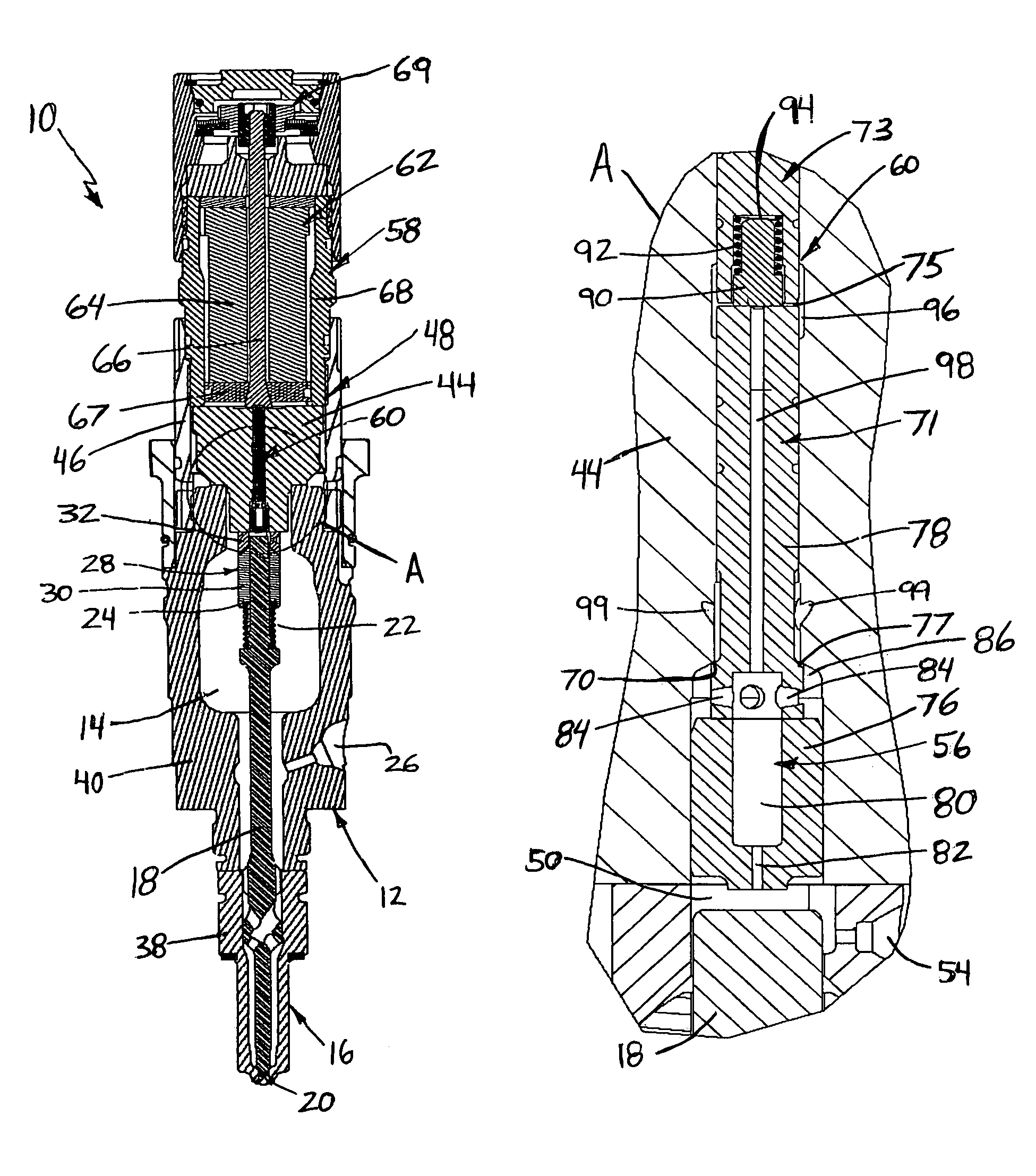
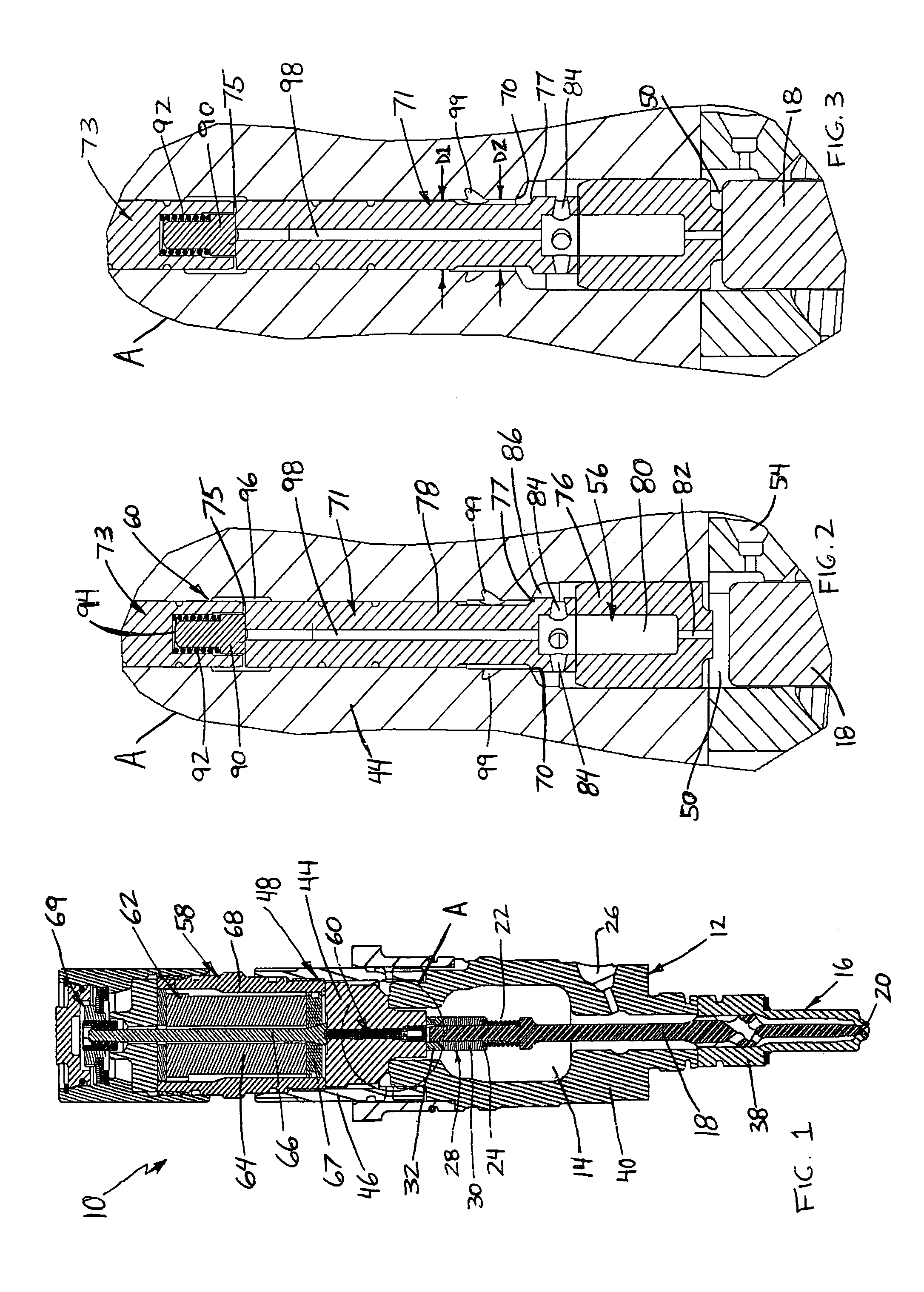
[0028]Referring to FIG. 1, there is shown a piezoelectric actuated fuel injector of the present invention, indicated generally at 10, which functions to effectively permit accurate and variable control of fuel metering by, in part, providing an improved, high preload on the piezoelectric stack using a simple, reliable, low cost approach. Fuel injector 10 is comprised of an injector body 12 having a generally elongated, cylindrical shape which forms an injector cavity 14. The lower portion of fuel injector body 12 includes a closed nozzle assembly, indicated generally at 16, which includes a nozzle valve element 18 reciprocally mounted for opening and closing injector orifices 20 formed in body 12 thereby controlling the flow of injection fuel into an engine combustion chamber (not shown).

[0029]Nozzle valve element 18 is preferably formed from a single integral piece structure and positioned in one end of injector cavity 14. A bias spring 22 is positioned in injector cavity 14 for ab...


PUM


Abstract

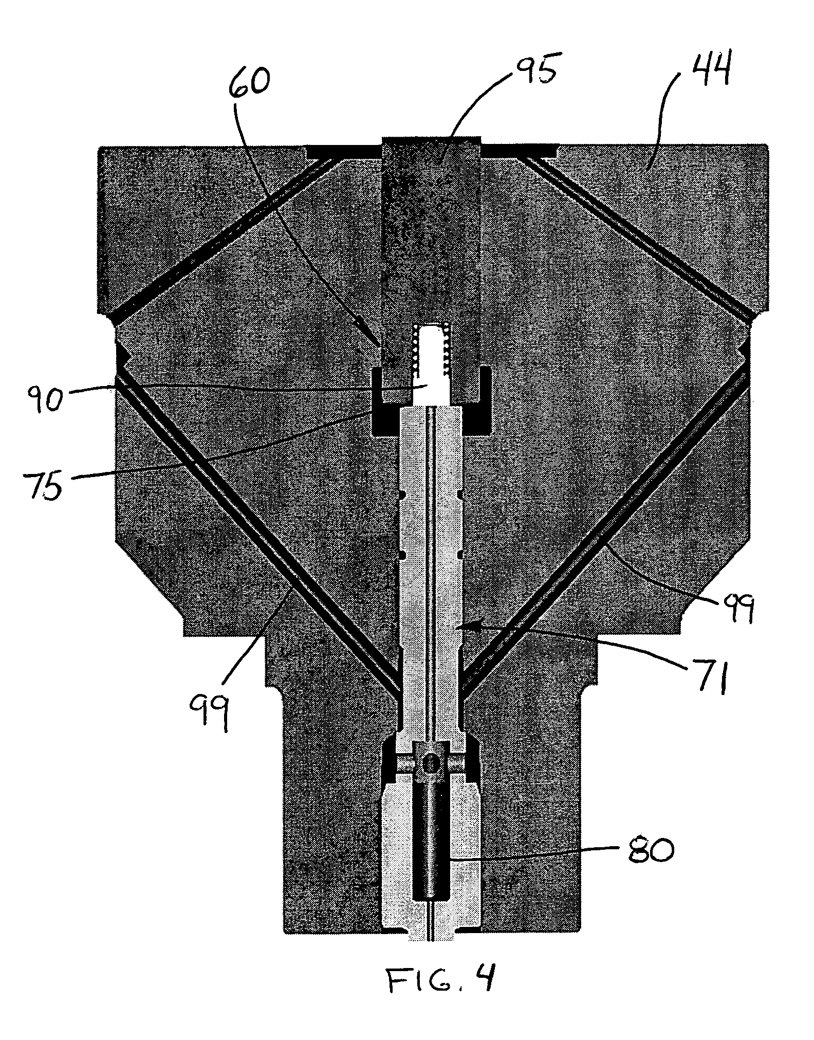
An piezoelectric actuated injector is provided which includes a nozzle valve element, a control volume, and an injection control valve including a control valve member for controlling fuel flow from the control volume so as to control nozzle valve movement. Importantly, the injector includes a preload chamber positioned along an injection control valve member for receiving high pressure fuel. The high pressure fuel acts on the injection control valve member to apply a preload force to supply a preload force to the stack of piezoelectric elements thereby ensuring more accurate control over fuel injection timing and metering.

Description

TECHNICAL FIELD[0001]The invention relates to an improved piezoelectric actuated fuel injector which effectively controls fuel metering while maintaining optimum preload on the piezoelectric actuator throughout operation.BACKGROUND OF THE INVENTION[0002]In most fuel supply systems applicable to internal combustion engines, fuel injectors are used to direct fuel pulses into the engine combustion chamber. A commonly used injector is a closed-nozzle injector which includes a nozzle assembly having a spring-biased nozzle valve element positioned adjacent the nozzle orifice for resisting blow back of exhaust gas into the pumping or metering chamber of the injector while allowing fuel to be injected into the cylinder. The nozzle valve element also functions to provide a deliberate, abrupt end to fuel injection thereby preventing a secondary injection which causes unburned hydrocarbons in the exhaust. The nozzle valve is positioned in a nozzle cavity and biased by a nozzle spring to block ...

Claims


Application Information

Patent Timeline
IPC IPC(8): F02M51/06B05B3/00F02M47/02
CPCF02M47/027F02M61/167F02M63/0026F02M63/0031
Inventor RAUZNITZ, PETERBUCHANAN, DAVID L.PETERS, LESTER L.
Owner CUMMINS INC
Learn More