
System and method for improving performance of an adaptive antenna array in a vehicular environment

Inactive Publication Date: 2006-11-21
SAMSUNG ELECTRONICS CO LTD
View PDF13 Cites 26 Cited by
  • Summary
  • Abstract
  • Description
  • Claims
  • Application Information

AI Technical Summary

Benefits of technology

[0014]To address the deficiencies of the prior art, it is a primary object of the present invention to provide, for use in wireless network, a system and method for improving downlink performance of an adaptive antenna array in a vehicular environment.
[0017]It is an object of the present invention to provide an improved system and method for improving the downlink performance and the uplink performance of an adaptive antenna array in a vehicular environment.
[0019]It is another object of the present invention to provide an improved system and method for providing a spatial signature estimator that is capable of obtaining a first set of spatial signatures and a second set spatial signatures within an uplink interval.

Problems solved by technology

Those skilled in the art will recognize that fading of the signal in a vehicular environment can sometimes produce signal strength variations in excess of thirty decibels (30 dB) and significantly degrade system performance.
Under such circumstances, many burst errors can occur within a relatively short time interval.
However, this technique wastes available frequency bandwidth by introducing the extra redundant bits.
Coding techniques are inefficient with respect to utilization of available bandwidth.
However, they are not well suited for a mobile station within a vehicular environment where a mobile station moves rapidly with respect to a base transceiver station.
As in the case previously described for non-adaptive antenna arrays, problems arise when a mobile station is moving relatively rapidly with respect to a base transceiver station.

Method used


Image

  • System and method for improving performance of an adaptive antenna array in a vehicular environment
  • System and method for improving performance of an adaptive antenna array in a vehicular environment
  • System and method for improving performance of an adaptive antenna array in a vehicular environment

Examples


Embodiment Construction

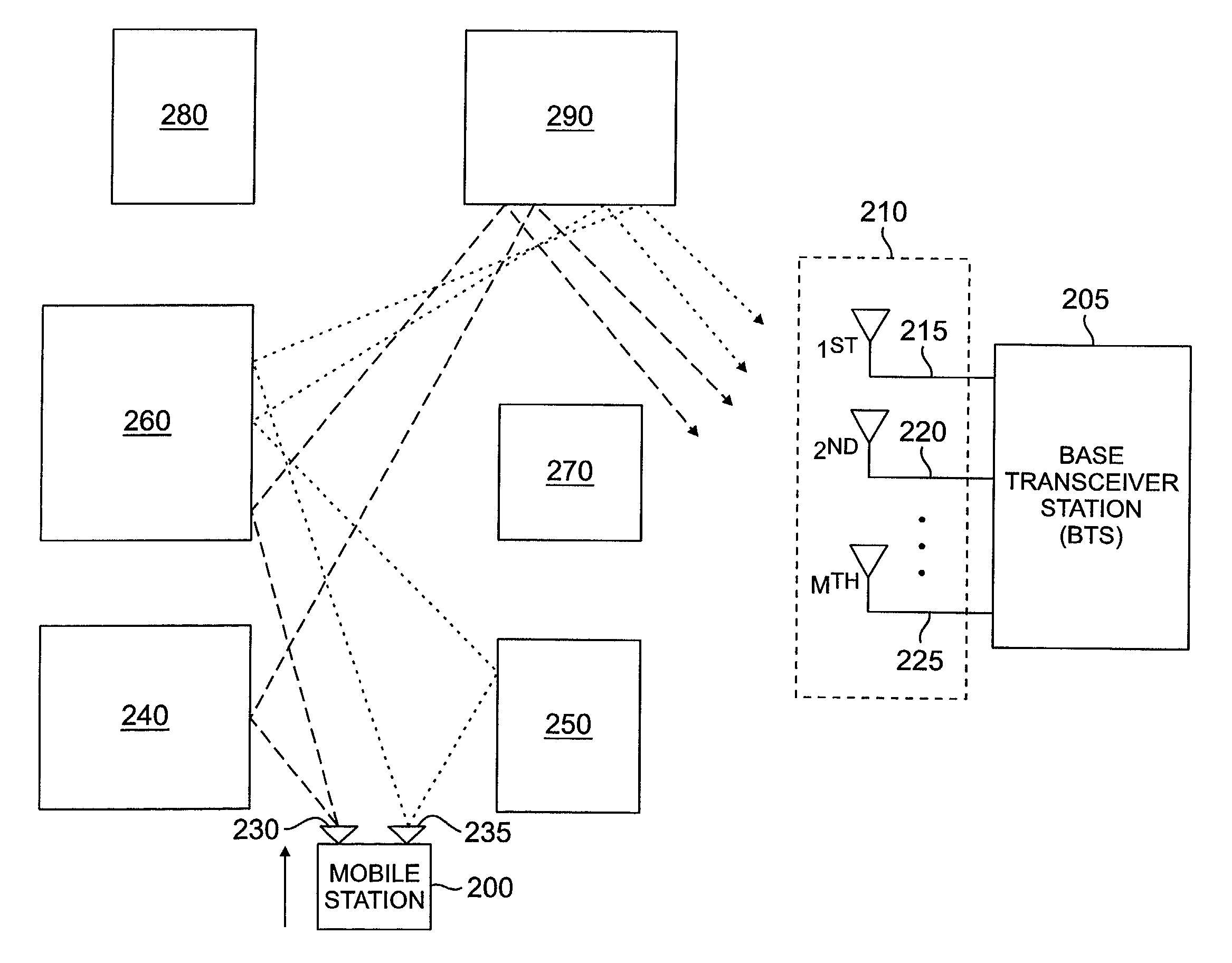
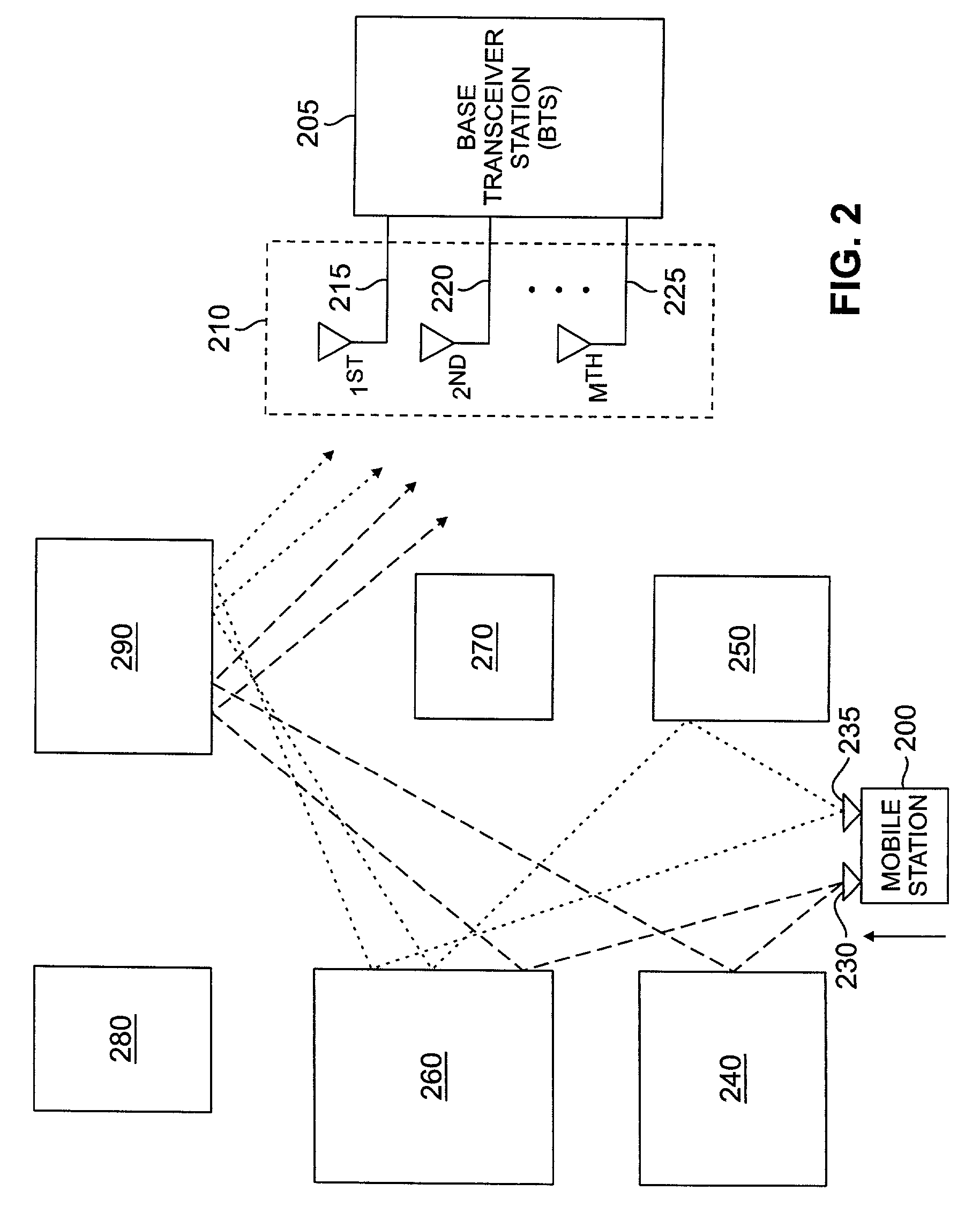
[0029]FIGS. 1 through 5, discussed below, and the various embodiments used to describe the principles of the present invention in this patent document are by way of illustration only and should not be construed in any way to limit the scope of the invention. Those skilled in the art will understand that the principles of the present invention may be implemented in any suitably arranged wireless network.

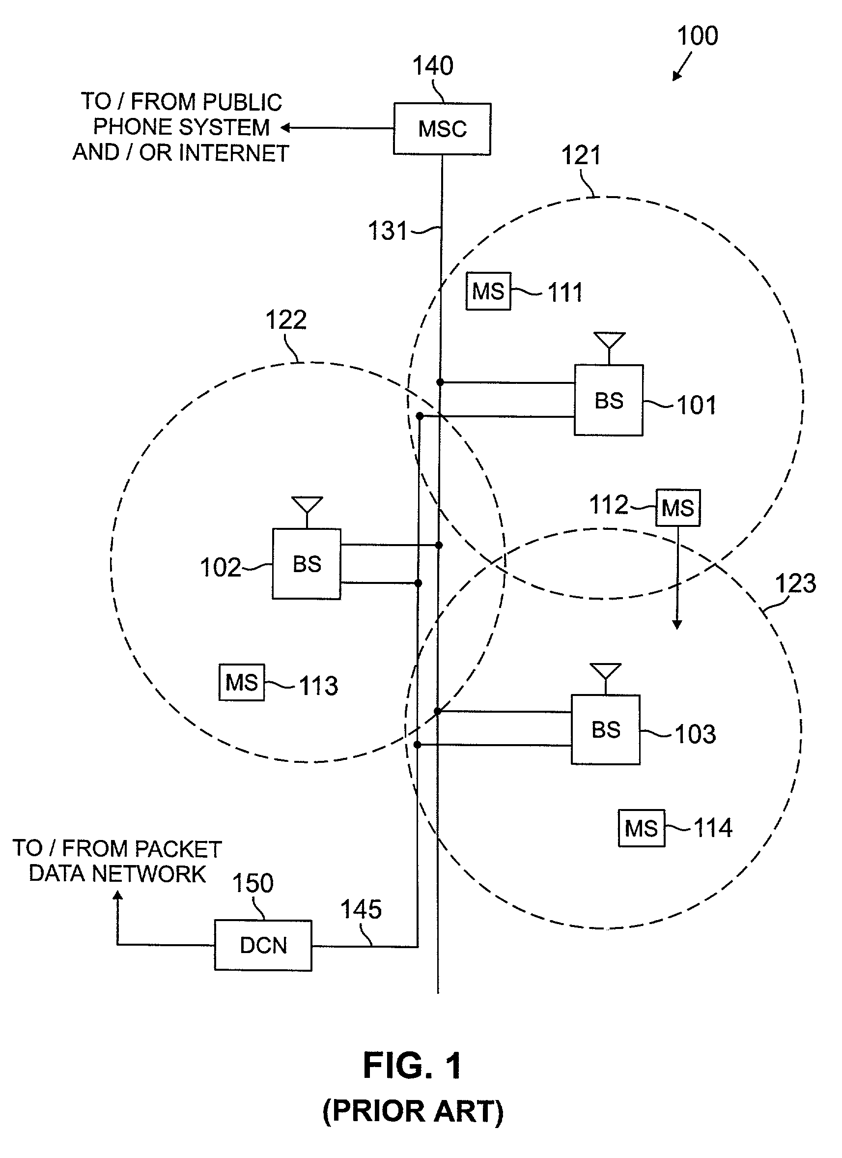
[0030]FIG. 1 illustrates a general overview of an exemplary wireless network 100. The wireless telephone network 100 comprises a plurality of cell sites 121–123, each containing one of the base stations, BS 101, BS 102, or BS 103. Base stations 101–103 are operable to communicate with a plurality of mobile stations (MS) 111–114. Mobile stations 111–114 may be any suitable wireless communication devices, including conventional cellular telephones, PCS handsets, portable computers, telemetry devices, and the like, which are capable of communicating with the base stations via wireless li...


PUM


Abstract

A system and method is disclosed for improving downlink performance of an adaptive antenna array in a vehicular environment. The system comprises a mobile station that has a first mobile antenna and a second mobile antenna. A spatial signature estimator associated with a base transceiver station obtains spatial signatures from signals from the first mobile antenna and from the second mobile antenna within an uplink interval. Correlation circuitry uses the spatial signatures to identify a least changing spatial signature to obtain an optimal downlink beamforming weight vector to be used in the transmission of a signal to the mobile station in the next downlink interval.

Description

TECHNICAL FIELD OF THE INVENTION[0001]The present invention is directed, in general, to wireless telecommunications networks and, more specifically, to a system and method for improving the downlink performance of an adaptive antenna array in a vehicular environment.BACKGROUND OF THE INVENTION[0002]The use of wireless networks has become increasingly widespread. A wireless mobile station (e.g., a cellular telephone) that is used within a moving vehicle may be moving relatively fast with respect to a base transceiver station (BTS). It is common for a wireless mobile station within a moving vehicle to reach speeds of thirty miles per hour (30 mph) to fifty miles per hour (50 mph) or more. When a wireless mobile station is moving relatively fast, the signal level received at the base transceiver station (BTS) fluctuates rapidly due to the fast fading of the wireless propagation channel. The rapid fluctuations of the received signal level are created as the vehicle that is carrying the ...

Claims


Application Information

Patent Timeline
IPC IPC(8): H04M1/00H04B7/155H04B7/06H04B7/08
CPCH04B7/0617H04B7/086H04B7/155
Inventor KAVAK, ADNANCLEVELAND, JOSEPH
Owner SAMSUNG ELECTRONICS CO LTD
Learn More