
Sensor head component

a technology of sensor head and component, applied in the field of components, can solve the problems of high cost, high cost, and high cost of each unit, and achieve the effect of reducing the cost of components

Active Publication Date: 2006-11-21
INSITU INC
View PDF16 Cites 72 Cited by
  • Summary
  • Abstract
  • Description
  • Claims
  • Application Information

AI Technical Summary

Benefits of technology

[0012]For a sensor head component configured as a sensor, the included electrical component enclosed within the housing may comprise a sensing element ...

Problems solved by technology

A significant issue with regards to the employment of tool assemblies for monitoring water quality conditions is the relatively high cost of each unit.
One reason for the high cost is that they use expensive components and designs that frequently require a significant amount of expensive machining and assembly.
The tools assemblies often require the complex assembly of many components and significant manufacturing expenses are often required to provide structures for coupling the components and for electrically interconnecting the components.
Furthermore, assembly and disassembly of components of the down-hole tools frequently require the use of wrenches or other tools, and sometimes special tools.
This complicates use of the down-hole monitoring tools, and providing features on the down-hole tools to accommodate tools required for assembly and disassembly often requires machining, which significantly adds to manufacturing costs.
Furthermore, electrical interconnections between components typically require special keying of the components, or of the electrical connectors between the components which result in difficulty of use and a possibility for tool damage or malfunction due to misalignment.
In addition to the high cost of monitoring wells and down-hold monitoring tools, a significant amount of ongoing labor is typically required to maintain the tools and to obtain and use data collected by the tools.
Moreover, many down-hole tools are difficult to service and must be returned to manufacturers and distributors for even relatively simple service tasks such as changing batteries in the tool.

Method used


Image

  • Sensor head component
  • Sensor head component
  • Sensor head component

Examples


Embodiment Construction

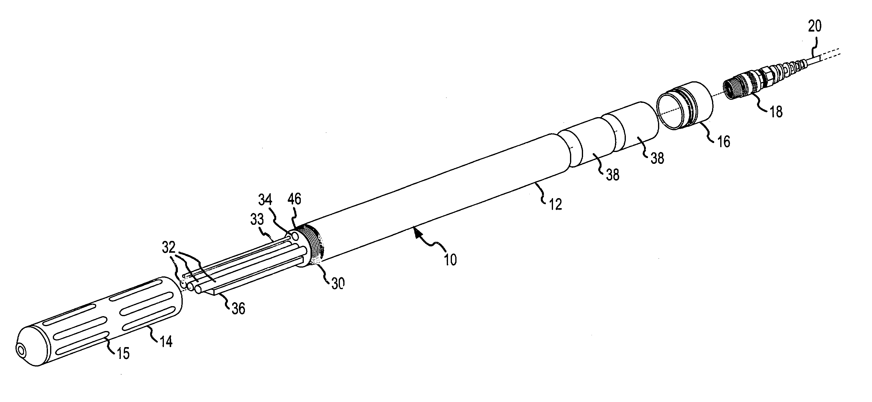
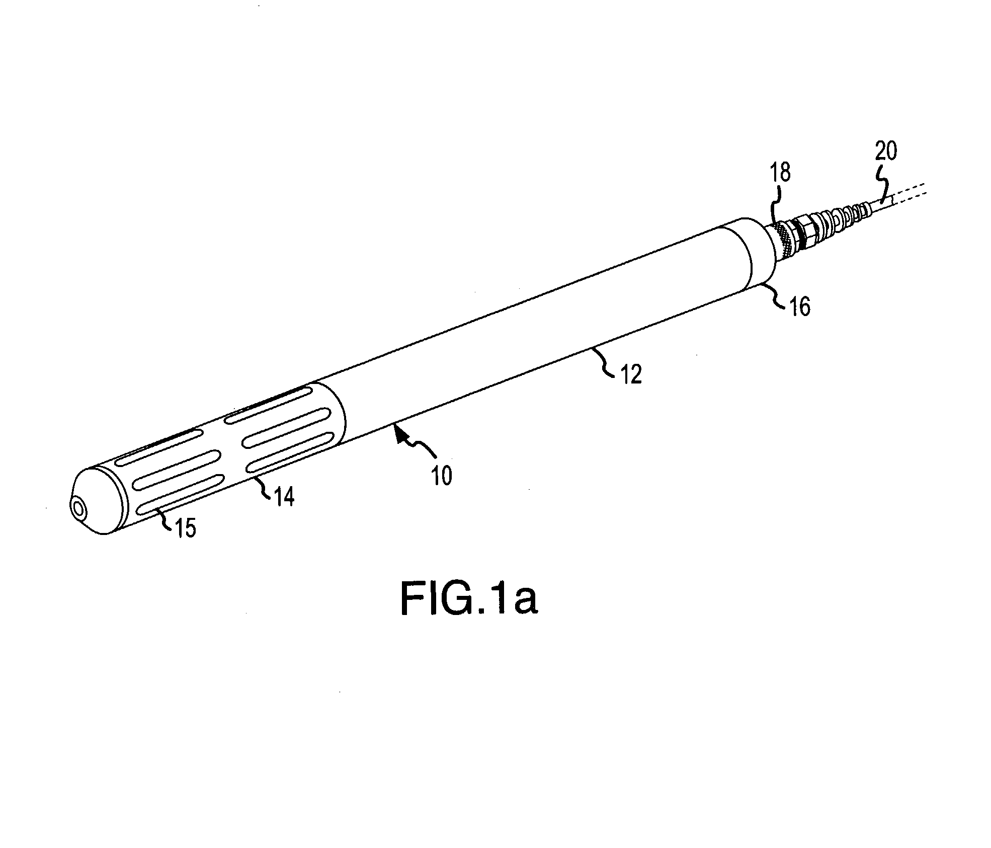
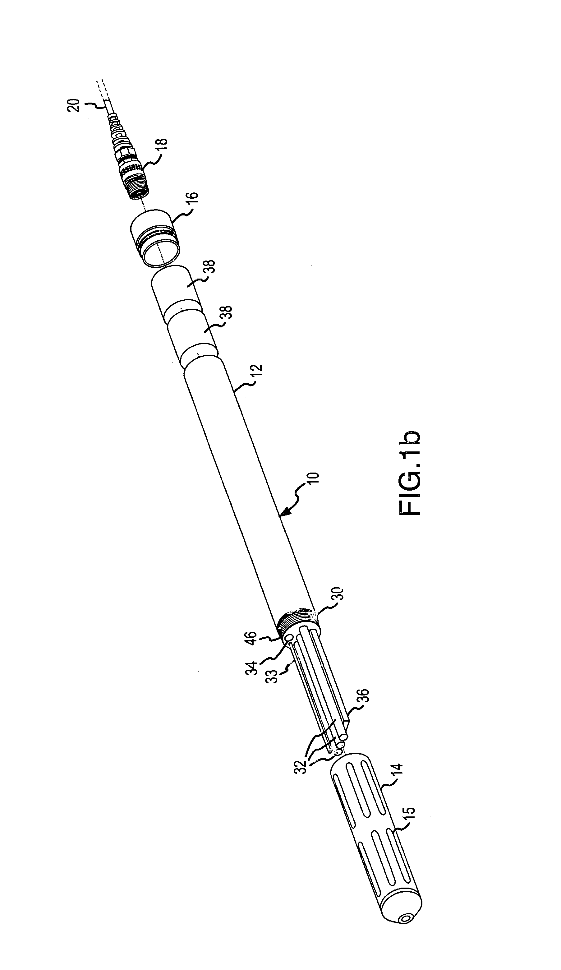
[0039]The present invention comprises a multi-parameter tool assembly employable for monitoring conditions in any number of locations, including ground and / or surface water, as well as within a flow cell. These locations may include insertion into a well or other hole. Specifically included in the multi-parameter tool assembly is a sensor head specially configured to receive and interconnect with one or more sensor head components. The sensor head components may comprise such things as a sensor or an accessory. The sensors may each be employable for monitoring a particular parameter. Further included in the multi-parameter tool assembly is an electronic system configured to direct at least one operation of the tool assembly and preferably substantially all operations. The electronic system may include a processor and memory having stored instructions readable and executable so as to direct operation. When one or more sensors are mounted in the sensor head, the computing unit is conf...


PUM


Abstract

A sensor head component is configured for use with a monitoring tool assembly in the performance of one or functions as part of a monitoring process. The sensor head component is configured to include at least one electrical component for performing the function as well as a memory device upon which operational information for the component is storable. The sensor head component is further configured to include an elongated body within which the electrical component is positionable and a base portion connectable to the elongated housing which further provides for mechanical and electrical engagement in a port for the tool assembly through application of a linear force.

Description

FIELD OF THE INVENTION[0001]The present invention relates to a components which are employable with a multi-parameter tool assembly, and more particularly to a sensor and / or accessory devices which are electrically and mechanically engagable in sensor head for a tool assembly and are employable for use in one or more monitoring processes.BACKGROUND OF THE INVENTION[0002]An ever increasing emphasis is being placed on systematic monitoring of environmental conditions in relation to ground and surface water resources. Examples of some situations where monitoring of conditions of a water resource may be desired include environmental monitoring of aquifers at an industrial site to detect possible contamination of the aquifer, monitoring the flow of storm water runoff and storm runoff drainage patterns to determine the affects on surface water resources, monitoring the flow or other conditions of water in a watershed from which a municipal water supply is obtained, monitoring lake, stream...

Claims


Application Information

Patent Timeline
IPC IPC(8): G08B23/00G01D11/24G01D21/02G01V11/00
CPCG01D11/24G01D21/02G01V11/002Y10S439/913Y10S439/955
Inventor HENRY, KENT D.WATSON, MARK A.ONKEN-SHAW, SHANENHOCHWITZ, TODD
Owner INSITU INC
Learn More