
Electrophysiological measurement method and system for positioning an implantable, hearing instrument transducer

a technology of implantable hearing instruments and electrophysiology, applied in the field of electrophysiology measurement methods and systems for positioning implantable hearing instruments, can solve the problems of degrading mechanical performance, degrading hearing, and ineffective communication of vibrations, and achieve the effect of facilitating the positioning of implantable transducers

Active Publication Date: 2006-11-21
COCHLEAR LIMITED
View PDF56 Cites 22 Cited by
  • Summary
  • Abstract
  • Description
  • Claims
  • Application Information

AI Technical Summary

Benefits of technology

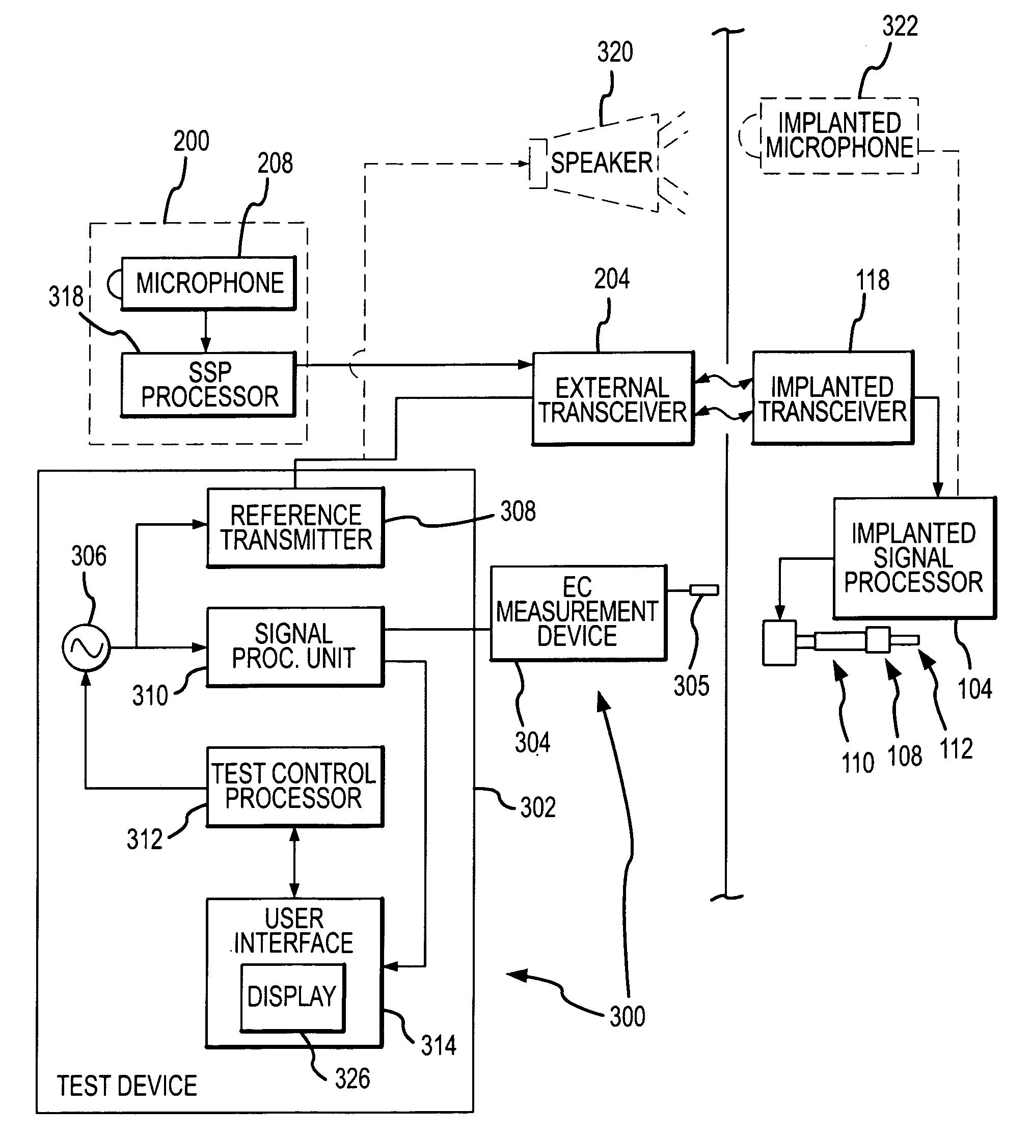
The present invention provides a method and system for positioning an implantable hearing instrument transducer relative to a middle ear component or inner ear of a patient. The method involves measuring electrophysiological responses to test signals and processing the signals to provide an output signal that indicates the desirability of the position. The system includes an implantable transducer, a measurement device, and a processor for analyzing the measured responses. The position can be adjusted manually or using a controllable actuator. The invention allows for simplified and automated positioning of the implantable transducer, making the process easier and more efficient. A user interface is also provided for receiving the processor output and providing an indication of the desirability of the position.

Problems solved by technology

Overloading or biasing of the implantable transducer relative to the ossicular chain can result in degraded performance of the biological aspect (movement of the ossicular chain), possibly causing an additional impairment of hearing, as well as degraded performance of the mechanical aspect (movement of the transducer).
Further, if the implantable transducer is underloaded relative to the ossicular chain, e.g. a loose connection or no physical contact at all, vibrations may not be effectively communicated.
Over time, such aspects may change and additional pathological aspects may develop.

Method used


Image

  • Electrophysiological measurement method and system for positioning an implantable, hearing instrument transducer
  • Electrophysiological measurement method and system for positioning an implantable, hearing instrument transducer
  • Electrophysiological measurement method and system for positioning an implantable, hearing instrument transducer

Examples


Embodiment Construction

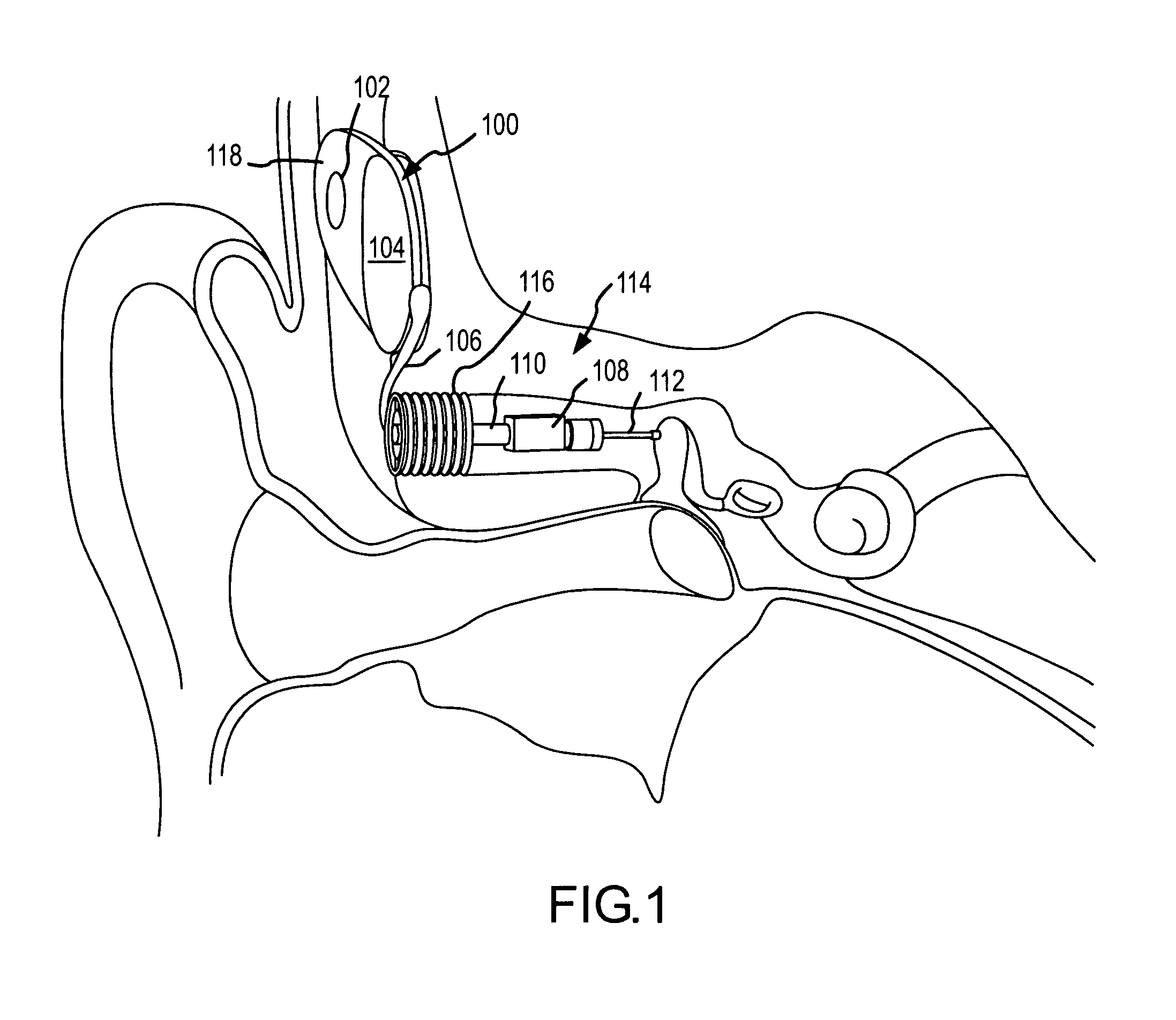
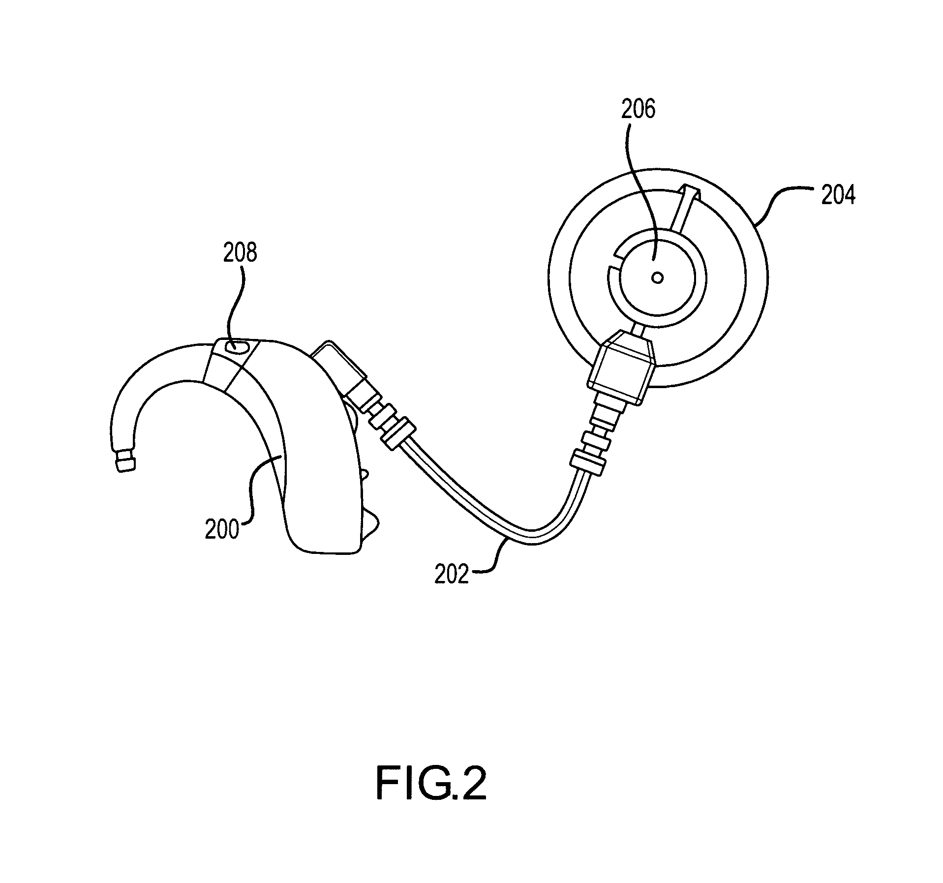
[0025]FIGS. 1 and 2 illustrate an example of a semi-implantable hearing instrument for a middle ear implementation. The implanted components are shown in FIG. 1 and the external components are shown in FIG. 2. As will be appreciated, the present invention may also be employed with fully implantable, middle ear hearing instruments, wherein all components of the hearing instrument are located subcutaneously. Further, the present invention may be employed for semi-implantable and / or fully implantable inner ear hearing instruments in which an implantable transducer is positioned relative to the inner ear of a patient, e.g. within the inner ear or in contact relation to the outside of the round window of the inner ear.

[0026]In the illustrated system, an implanted biocompatible housing 100 is located subcutaneously on a patient's skull. The housing 100 includes a wireless audio signal link receiver / transmitter 118 (e.g. an RF signal transceiver comprising a coil element) and a signal proc...


PUM


Abstract

An electrophysiological measurement method and system is provided for positioning an implantable transducer of a hearing instrument relative to a middle ear component or inner ear of a patient. The method and system employ electrophysiological measurement signals obtained in response to test signals applied to an implanted transducer. In one embodiment, the electrophysiological measurements are obtained by an electrocochleography measurement device that measures the cochlear summating potential and / or action potential responsive to test signals applied to an implanted transducer. In another embodiment, an auditory brainstem response measurement device is utilized to obtain electrical potential measurement signals responsive to test signals applied to an implanted transducer.

Description

CROSS-REFERENCE TO RELATED APPLICATIONS[0001]This application claims priority under 35 U.S.C. §119 to prior U.S. Provisional Patent Application Ser. No. 60 / 528,728, filed on Dec. 11, 2003, and entitled “ELECTROPHYSIOLOGICAL MEASUREMENT METHOD AND SYSTEM FOR ASSESSING A MIDDLE EAR INTERFACE OF AN IMPLANTABLE HEARING INSTRUMENT TRANSDUCER”, the disclosure of which is incorporated herein by reference in its entirety.FIELD OF THE INVENTION[0002]The present invention relates to the field of hearing instruments that include implanted transducers, and more particularly, to an electrophysiological measurement method and system for positioning an implantable hearing instrument transducer relative to a middle ear component or the inner ear of a patient.BACKGROUND OF THE INVENTION[0003]In the class of hearing aids generally referred to as implantable hearing instruments, some or all of various hearing augmentation componentry is positioned subcutaneously on or within a patient's skull, typical...

Claims


Application Information

Patent Timeline
Patent Type & Authority Patents(United States)
IPC IPC(8): H04R25/00A61B5/0484
CPCA61B5/04845H04R25/606A61B5/38
Inventor WALDMANN, BERND
Owner COCHLEAR LIMITED
Learn More