Optical scanner

a scanner and optical technology, applied in the field of optical scanners, can solve the problems of reducing the readability of barcodes, affecting the accuracy of scanning patterns, and increasing the cost of components, so as to improve the omni-directional item coverage, reduce the gap in coverage, and improve the effect of manufacturability

Inactive Publication Date: 2006-11-21
NCR VOYIX CORP
View PDF13 Cites 4 Cited by
  • Summary
  • Abstract
  • Description
  • Claims
  • Application Information

AI Technical Summary

Benefits of technology

[0006]The complexity of dual aperture scanners will be described in order to illustrate another advantage of the present invention, which is the simplicity and corresponding ease of construction of the scanner.
[0007]As will be illustrated in more detail below, with reference to FIGS. 1 to 6, present day scanners comprise, a laser assembly, spinner assembly, collection optics, pattern mirrors, detector assembly, electronics, a window and scanner housing which contains all the individual assemblies. In operation, the laser beam intercepts the polygon spinner rotating about a single axis and is subsequently scanned in a single plane towards a set of pattern mirrors which reflect the individual scan lines out the window and onto a barcode. The laser energy is then reflected off of the barcode and a portion is gathered by the collection optics and focused onto the detector generating a signal to be decoded by the electronics. The positions at which the scan lines exit the window are static, and are contained in a relatively small portion of the hemispherical volume available outside and adjacent to the window (FIG. 6). Consequently, the readability of barcodes is limited to certain orientations within that small scan volumeSUMMARY OF THE INVENTION
[0008]It would be desirable to provide an optical scanner with a reduction in coverage gaps and an improvement in omni-directional item coverage. It would also be desirable to provide a scan engine which can be utilized in an optically simpler barcode scanner (regardless of the number of scanner apertures) for improved manufacturability and reduced cost.
[0009]In accordance with a first aspect of the present invention there is provided an optical scanner comprising a scanner housing including a scan window, a laser light source, a reflected light detector and a mirrored polygon spinner which is arranged to spin around both a first axis of rotation and a second axis of rotation.
[0010]Preferably, the first and second axes of rotation are substantially orthogonal and the first axis of rotation is pointed to the scan window. In one embodiment it may be substantially parallel to the scan window.
[0012]In one embodiment the scanner further comprises pattern mirrors arranged to direct light from the polygon spinner through the scan window so as to produce scan lines.

Problems solved by technology

Problems of enhanced scan volume and increased readability of barcodes held at different orientations to a scanner are common to all barcode scanners (single and dual aperture scanners).
Although these problems have been best addressed by the use of dual aperture scanners, even these scanners produce scan patterns with gaps in item coverage.
The addition of these components consequently increases cost.
Consequently, the readability of barcodes is limited to certain orientations within that small scan volume

Method used


Image

  • Optical scanner
  • Optical scanner
  • Optical scanner

Examples


Embodiment Construction

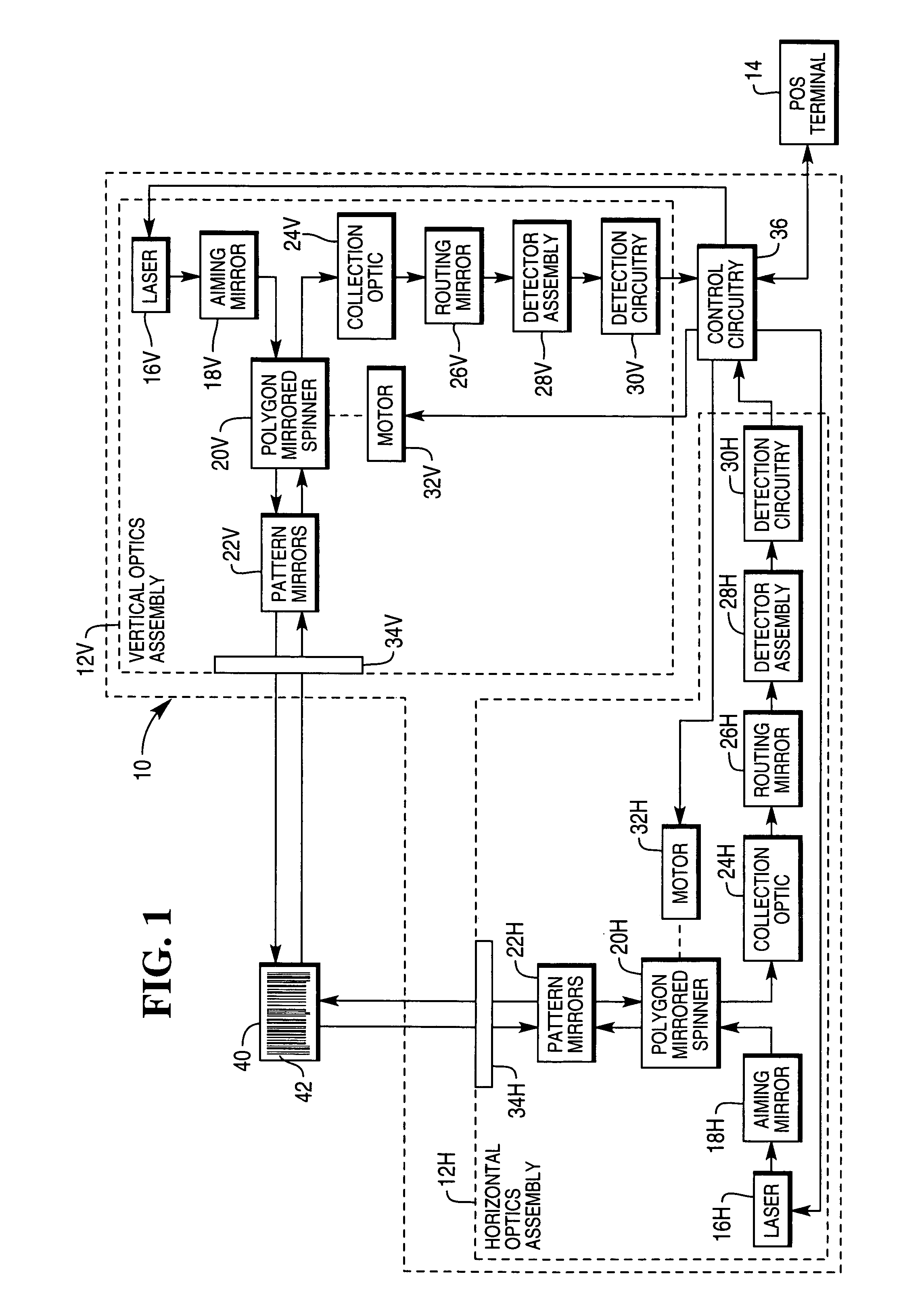
[0042]Referring now to FIG. 1, prior art dual aperture optical scanner 10 includes horizontal optics assembly 12H and vertical optics assembly 12V, and control circuitry 36 for controlling horizontal and vertical optics assemblies 12H and 12V. If one of optics assemblies 12H and 12V fails, scanner 10 retains partial operation.

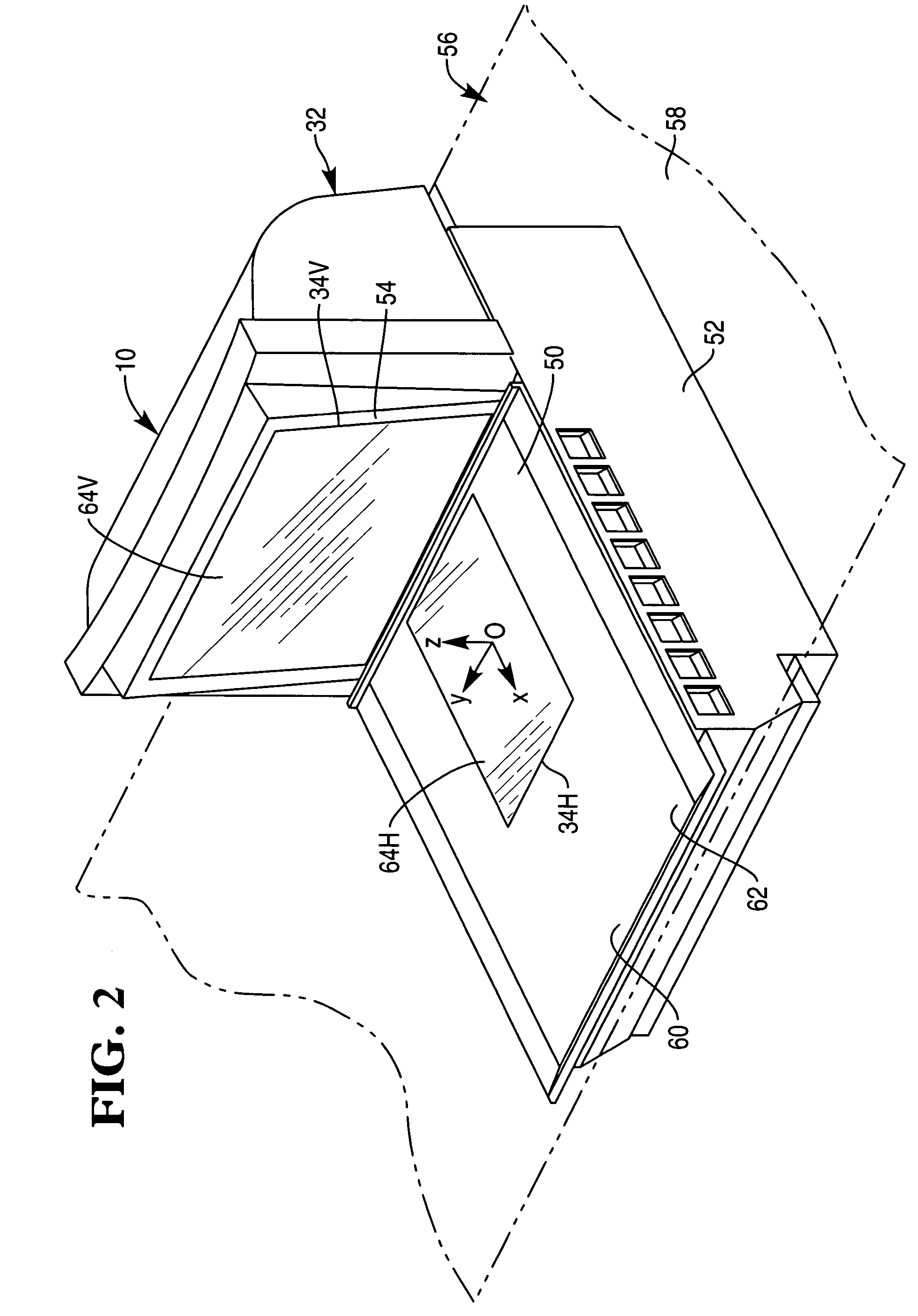
[0043]Horizontal optics assembly 12H projects a scan pattern through substantially horizontal aperture 34H to scan bar codes 42 located on bottom, leading, trailing and checker side surfaces of item 40. It will also scan bar codes 42 on intermediate surfaces including those between the bottom and customer side surfaces.

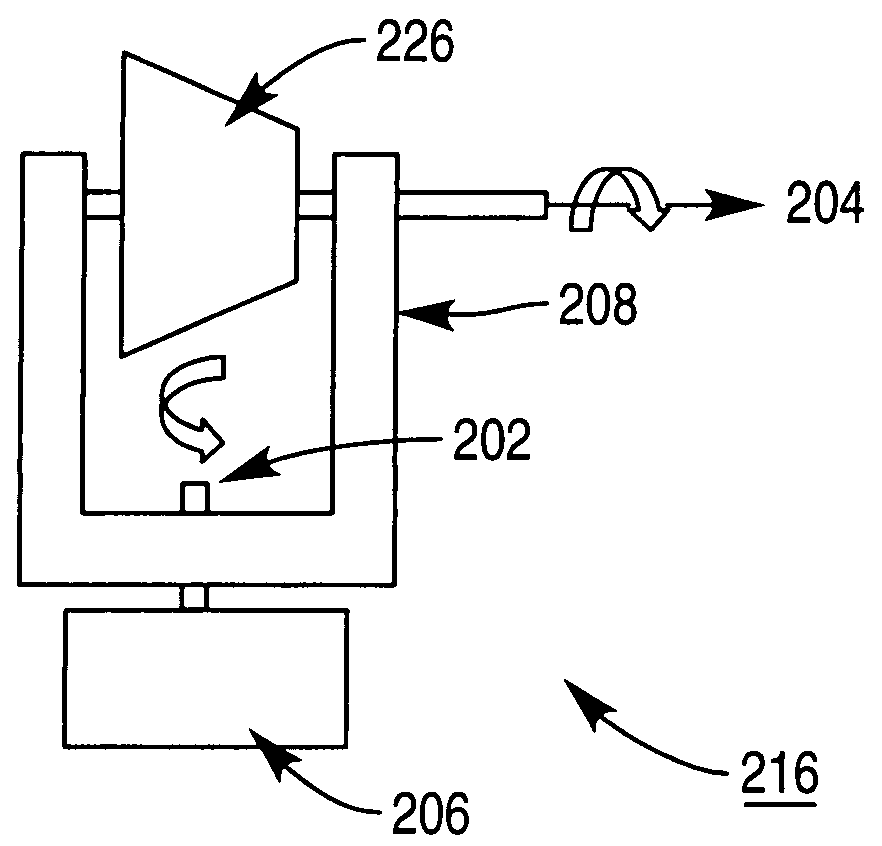
[0044]Horizontal optics assembly 12H includes laser 16H, aiming mirror 18H, polygon mirrored spinner 20H, pattern mirrors 22H, routing mirror 26H, collection optic 24H, detector assembly 28H, detection circuitry 30H, and motor 32H.

[0045]Laser 16H includes one or more laser diodes or other suitable laser sources. Laser 16H may include a laser havi...


PUM


Abstract

An optical scanner includes a scanner housing including a scan window, a laser light source, reflected light detector and a mirrored polygon spinner. The spinner is arranged to spin around both a first axis of rotation and a second axis of rotation so as to produce a substantially hemispherical scan volume.

Description

[0001]The present invention relates to an optical scanner and more specifically to an optical scanner having enhanced scan volume.BACKGROUND OF THE INVENTION[0002]Problems of enhanced scan volume and increased readability of barcodes held at different orientations to a scanner are common to all barcode scanners (single and dual aperture scanners). Although these problems have been best addressed by the use of dual aperture scanners, even these scanners produce scan patterns with gaps in item coverage. These gaps generally increase as the item is moved away from an ideal position in the center of the scan volume.[0003]Commonly assigned U.S. Pat. Nos. 5,229,588, 5,684,289, and 5,886,336 disclose a typical dual aperture optical scanner. The scanning light beams from a laser diode pass through substantially horizontal and vertical apertures to provide more item coverage than a single aperture scanner.[0004]Furthermore, in an effort to increase item coverage, optics designers are increas...

Claims


Application Information

Patent Timeline
Patent Type & Authority Patents(United States)
IPC IPC(8): G06K7/10G02B26/08
CPCG02B5/09G02B26/121G02B26/129G06K7/10613G06K7/10623G06K7/1096
Inventor HAMMER, STEVEN J.
Owner NCR VOYIX CORP
Why Eureka
Try Eureka