Automated Meds dispenser system

a dispenser system and automatic technology, applied in the field of medical devices, can solve the problems of reducing the effectiveness of medications, allergic reactions, cross-contamination, etc., and achieve the effect of preventing unauthorized access

Inactive Publication Date: 2006-11-21
CRYCO TWENTY TWO
View PDF10 Cites 16 Cited by
  • Summary
  • Abstract
  • Description
  • Claims
  • Application Information

AI Technical Summary

Benefits of technology

[0010]The general purpose of the present invention is to provide an automated Meds dispenser system which dispenses Meds on a timely basis. The automated Meds dispenser system, the present invention, includes an automated Meds dispenser and a staging station. Meds, such as pills and capsules, are distributed by the user or a health care professional into a plurality of vials systematically contained and arranged in a staging station having a matrix which is marked by days of the week and by Meds designation or by other such convenient markings. Vials containing the Meds are transferred from the staging station to the automated Meds dispenser for timed and systematic presentation one vial at a time by the automated Meds dispenser from which the vial is manually removed and the Meds consumed. A control panel is provided including a clock, a key operated multiple position switch, an audible warning device, verification lights, and various control buttons used for control of a microprocessor and of the mechanical functions of the automated Meds dispenser. A key can be used by a health care professional or by the user to prevent unauthorized access to or tampering with the automated Meds dispenser. An enclosure consists of a readily detached cover secured to a base, the combination of which houses the mechanical components of the automated Meds dispenser. Central to the enclosure is a pivoted round indexer plate in which a plurality of removable vials are held. An electric motor is incorporated to rotate the indexer plate to deliver one of a plurality of vials containing Meds to a delivery port located at the front of the enclosure. Optical sensor switches are incorporated to sense the indexer plate position and a solenoid is incorporated to prevent manual manipulation of the indexer plate to obtain Meds before the prescribed time. The program and thus the movement of the indexer plate can be interrupted to either add or remove Meds if desired, followed by the return of the indexer plate to a previous position without interrupting a scheduled program. A new schedule can be started before a predetermined schedule has been completed. A power failure feature is also included to deliver the Meds at the proper time and, in addition, the cover of the enclosure is readily detached from the base of the enclosure should a power failure occur and access to the Meds be required.
[0012]According to another aspect of the present invention, a substantially two-part staging station, being part of the automated Meds delivery system, is provided. The two-part staging station comprises a box-like structure with an upwardly located panel including a plurality of holes for accommodation of Meds vials and a cover which containingly fits over and about the sides of the box-like structure. The cover top engages the openings of the vials to prevent escape of the Meds from the vials.
[0018]Still another significant aspect and feature of the present invention is an automated Meds dispenser system in which the Meds are not subject to dragging about the bottom of a rotatable chamber.
[0025]Another significant aspect and feature of the present invention is an automated Meds dispenser system in which the enclosure can be readily dismantled to gain access to the Meds in case of a power failure.

Problems solved by technology

This sliding and grinding action between the Meds in the rotatable chamber and the stationary floor can lead to foreign particles being picked up, which could bring about contamination, thereby causing serious illness or reducing the effectiveness of the medications.
Further, after these “permanent chamber” models have been used and reloading occurs, with possibly different medications, cross-contamination could occur because of residue, granules or particles left over from previous use.
This circumstance could possibly cause allergic reactions in some instances or other complications.
Prior art Meds dispensation units are complicated, cumbersome and impractical and do not address all the safety concerns required when administering medications in this fashion.
Previous devices do not address power failure and its effect on an ongoing programmed schedule.

Method used


Image

  • Automated Meds dispenser system
  • Automated Meds dispenser system
  • Automated Meds dispenser system

Examples


Embodiment Construction

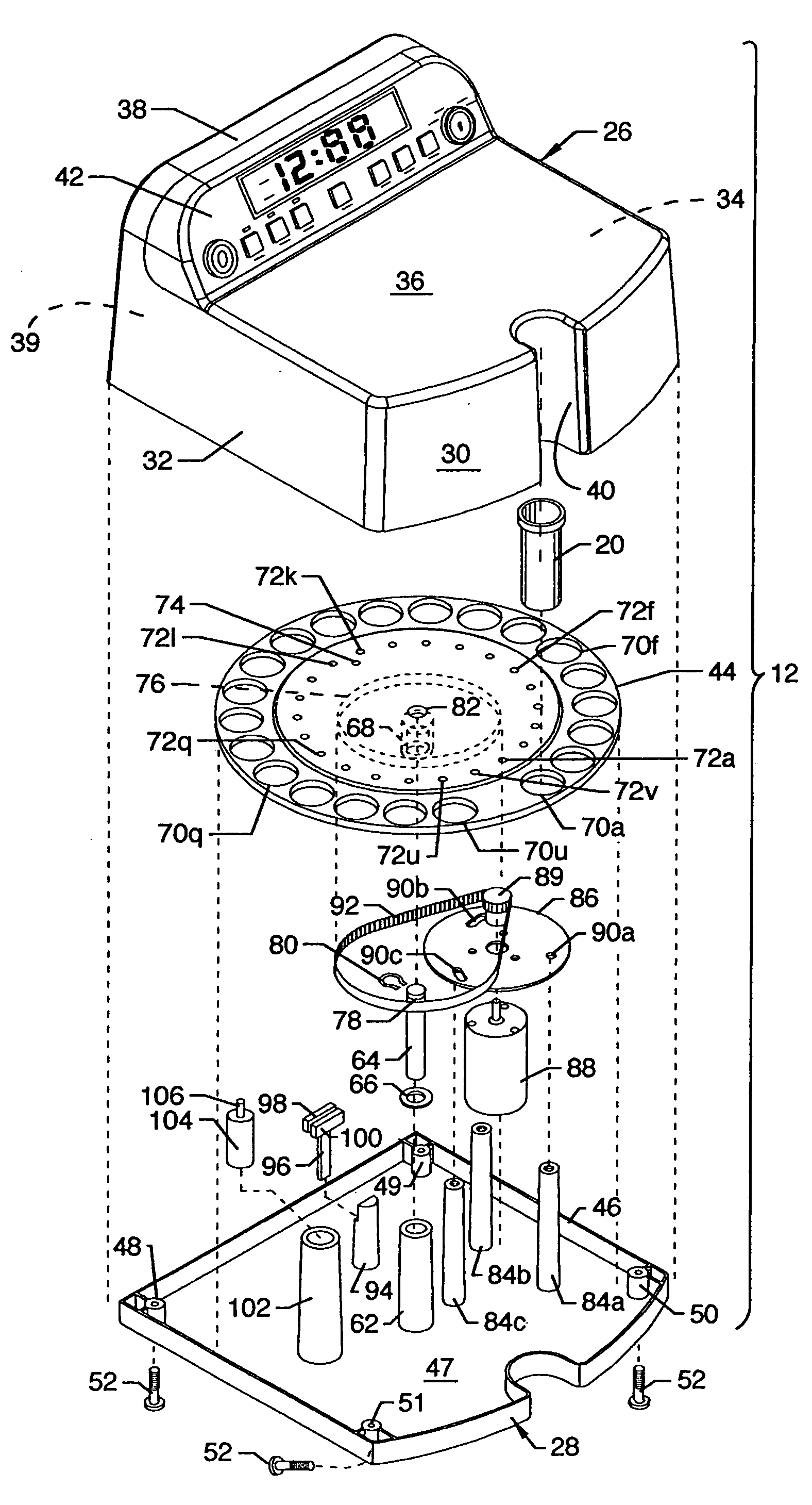
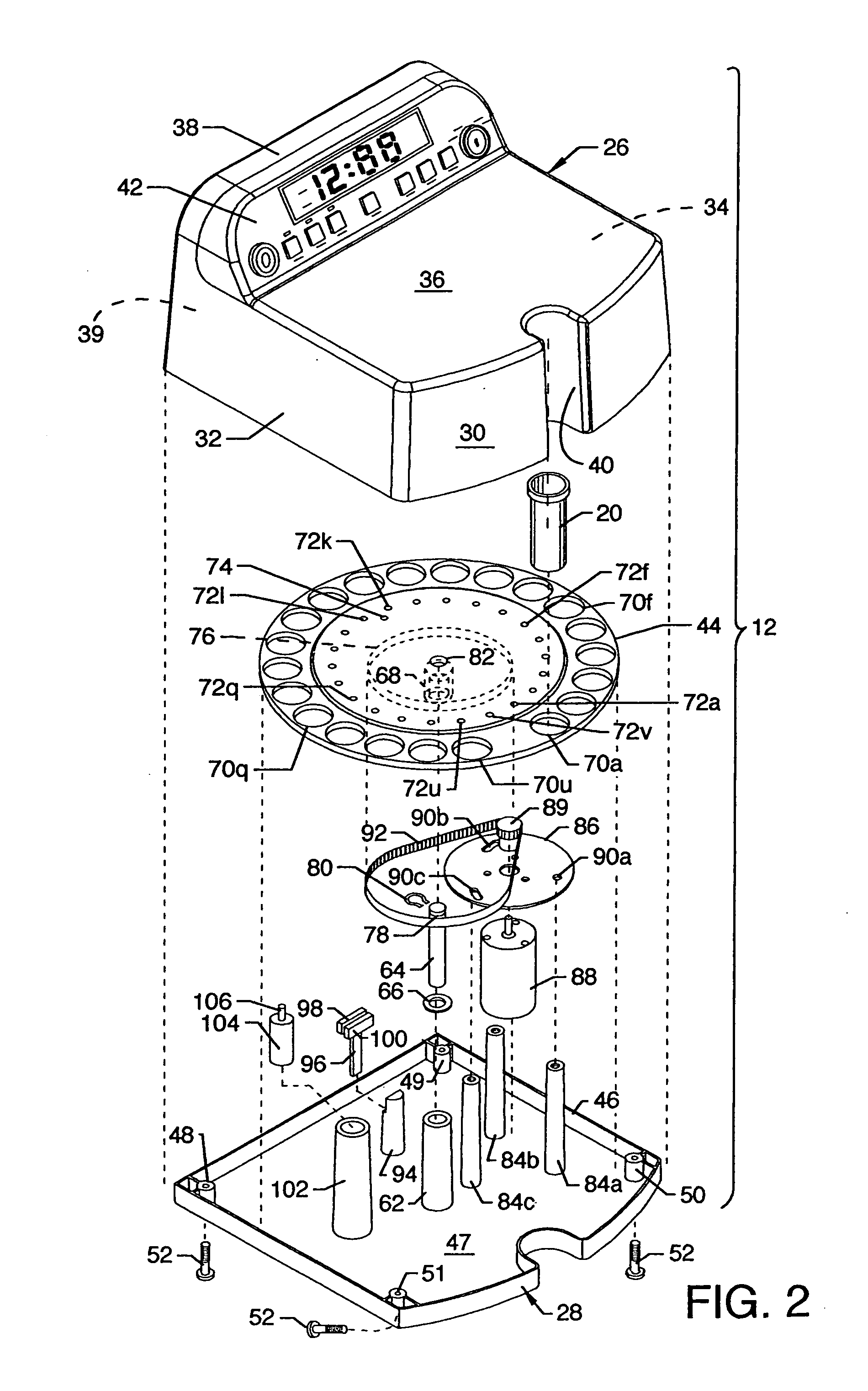
[0033]FIG. 1 is an isometric view of the automated Meds dispenser system 10, including an automated Meds dispenser 12 and a staging station 14. The staging station 14 includes a box 22 and a cover 13. The upper region of the box 22 includes a panel 18 having a matrix of holes 16a–16n extending therethrough for accommodation of a plurality of like vials 20, such as shown at the front edge of the automated Meds dispenser 12 and as shown in alignment with one of the holes 16a–16n. The holes 16a–16n in the matrix are identified by labels such as, but not limited to, MED 1 through MED 3 along one edge of the panel 18 and by the days of the week along an intersecting edge, and can be round or of other desired and other suitable shapes as required. The panel 18 is supported by other structure of the box 22 including four sides 22a, 22b, 22c and 22d and a bottom 22e. The cover 13 can be an open bottom box-like structure having a top 13a and sides 13b, 13c, 13d and 13e where the sides snugly...


PUM


Abstract

An automated Meds dispenser system including a staging station for systematic loading of Meds into vials and an automated Meds dispenser for receiving and for subsequent distribution of Meds containing vials at multiple times over a period of multiple days. User friendly on-board circuitry and controls are provided to set the desired Meds distribution times. A positionable indexer plate accommodates the vials containing Meds which are loaded by the user or health care professional and subsequently distributed and presented by the automated Meds dispenser on a timely basis one vial at a time for use by a patient. The positionable indexer plate is advanced one position at a time as specified and stored in an onboard programmable microprocessor.

Description

CROSS REFERENCES TO RELATED APPLICATIONS[0001]None.BACKGROUND OF THE INVENTION[0002]1. Field of the Invention[0003]The present invention pertains to the medical field, and more particularly, pertains to an automated Meds dispenser system where an automated Meds dispenser programmed by a user or health care professional presents medicines in pill or capsule form for use at designated time intervals.[0004]2. Description of the Prior Art[0005]Prior art pill or capsule dispensers include units incorporating one or more rotatable “permanent chambers” of varying size and shape in which Meds, an abbreviation commonly used for medications, are stored while waiting to be dispensed. Meds, when placed in these rotatable “permanent chamber” models, fall naturally with the aid of gravity to the floor of the rotatable chamber. The chamber floor, however, is a separate stationary plate / disc with a hole at one location, thereby allowing the Meds to pass through the hole when the rotatable chamber p...

Claims


Application Information

Patent Timeline
IPC IPC(8): G07F11/00
CPCG07F9/02G07F11/54G07F17/0092
Inventor YATES, CLEON R.GUTHRIE, JOE S.
Owner CRYCO TWENTY TWO
Why Eureka
Try Eureka