
Method and apparatus for determining instantaneous inspired volume of a subject during ventilatory assistance

a technology of instantaneous inspired volume and apparatus, which is applied in the direction of application, diagnostic recording/measuring, operating means/releasing devices of valves, etc., can solve the problems of reducing the efficiency of the device, affecting the comfort or panic of patients, and affecting the comfort of patients,

Inactive Publication Date: 2006-11-21
RESMED LTD
View PDF451 Cites 227 Cited by
  • Summary
  • Abstract
  • Description
  • Claims
  • Application Information

AI Technical Summary

Benefits of technology

[0032]The invention further discloses a method for calculating instantaneous phase in the respiratory cycle as a continuous variable, as described above, in which the step of calculating respiratory airflow includes a low pass filtering step to reduce non-respiratory noise, in which the time constant of the low pass filter is an increasing function of an estimate of the length of the respiratory cycle.

Problems solved by technology

Most known ventilatory devices do not accurately match the amplitude and phase of mask pressure to the subject's spontaneous efforts, leading to discomfort or panic.
Larger amounts of asynchrony also reduce the efficiency of the device.
Therefore, unless the device can automatically adjust the degree of support, the amplitude of delivered pressure will either be inadequate during sleep, or must be excessive in the awake state.
Furthermore, during sleep there are inevitably large leaks between mask and subject, or at the subject's mouth if this is left free.
Such leaks worsen the error in matching the phase and magnitude of the machine's effort to the subject's needs, and, in the case of mouth leak, reduce the effectiveness of the ventilatory support.
All such simple devices fail to meet goal (ii) of adjusting the degree of assistance to maintain at least a given ventilation.
They also largely fail to meet goal (i) of closely matching the subject's respiratory phase: timed devices make no attempt to synchronize with the subject's efforts; triggered devices attempt to synchronize the start and end of the breath with the subject's efforts, but make no attempt to tailor the instantaneous pressure during a breath to the subject's efforts.
Furthermore, the triggering tends to fail in the presence of leaks, thus failing goal (iii).
A disadvantage of calculating V(t) in this way is that, in the presence of leaks, the integral of the flow through the leak will be included in V(t), resulting in an overestimation of V(t), in turn resulting in a runaway increase in the administered pressure.
This can be distressing to the subject.
Secondly, PAV relies on the subject's chemoreceptor reflexes to monitor the composition of the arterial blood, and thereby set the level of spontaneous effort.
In subjects with abnormal chemoreceptor reflexes, the spontaneous efforts may either cease entirely, or become unrelated to the composition of the arterial blood, and amplification of these efforts will yield inadequate ventilation.
In patients with existing Cheyne Stokes breathing during sleep, PAV will by design amplify the subject's waxing and waning breathing efforts, and actually make matters worse by exaggerating the disturbance.
Thus PAV substantially meets goal (i) of providing assistance in phase with the subject's spontaneous ventilation, but cannot meet goal (ii) of adjusting the depth of assistance if the subject has inadequate chemoreflexes, and does not satisfactorily meet goal (iii).
Thus there are known devices that meet each of the above goals, but there is no device that meets all the goals simultaneously.

Method used


Image

  • Method and apparatus for determining instantaneous inspired volume of a subject during ventilatory assistance
  • Method and apparatus for determining instantaneous inspired volume of a subject during ventilatory assistance
  • Method and apparatus for determining instantaneous inspired volume of a subject during ventilatory assistance

Examples


first embodiment

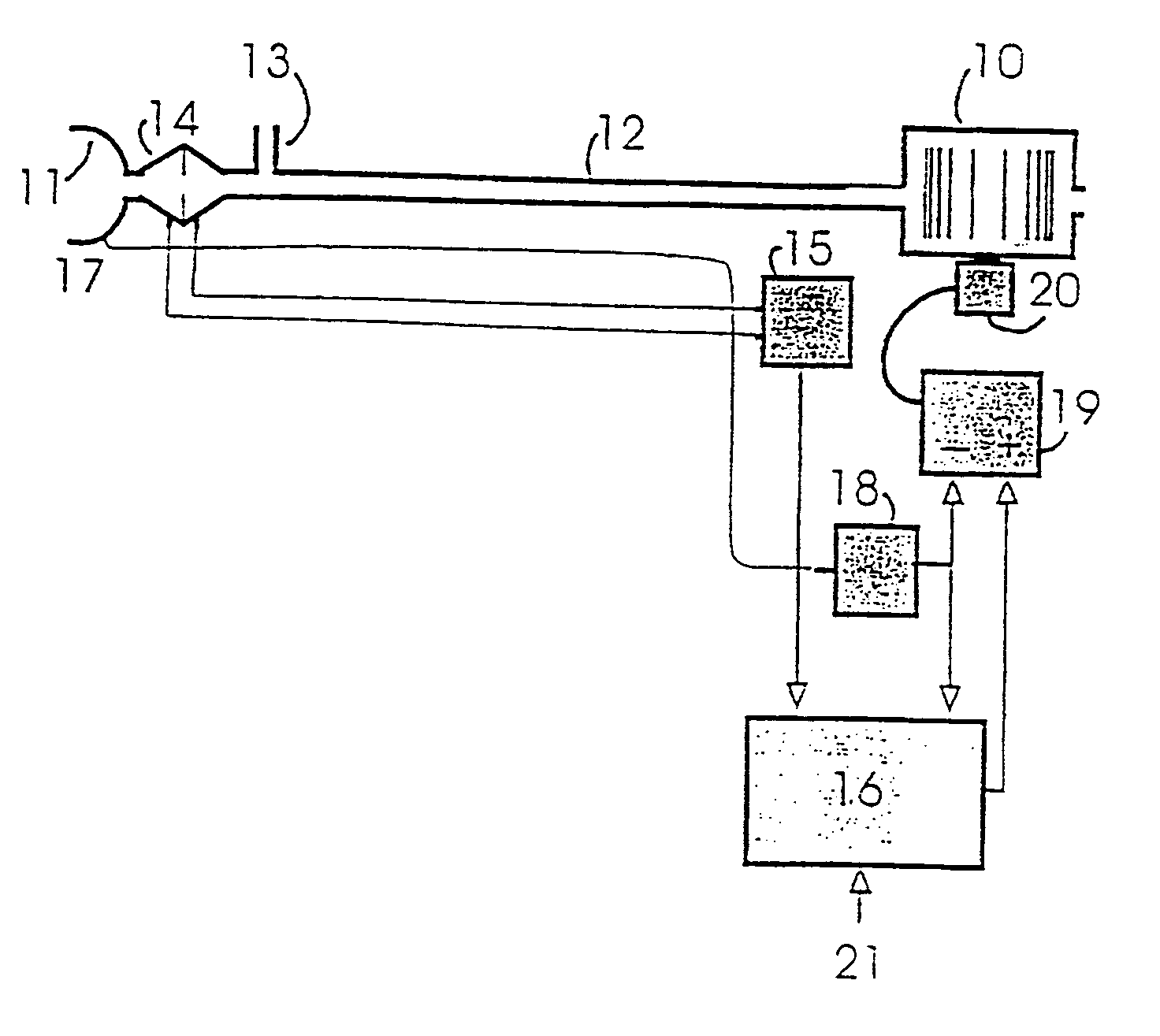
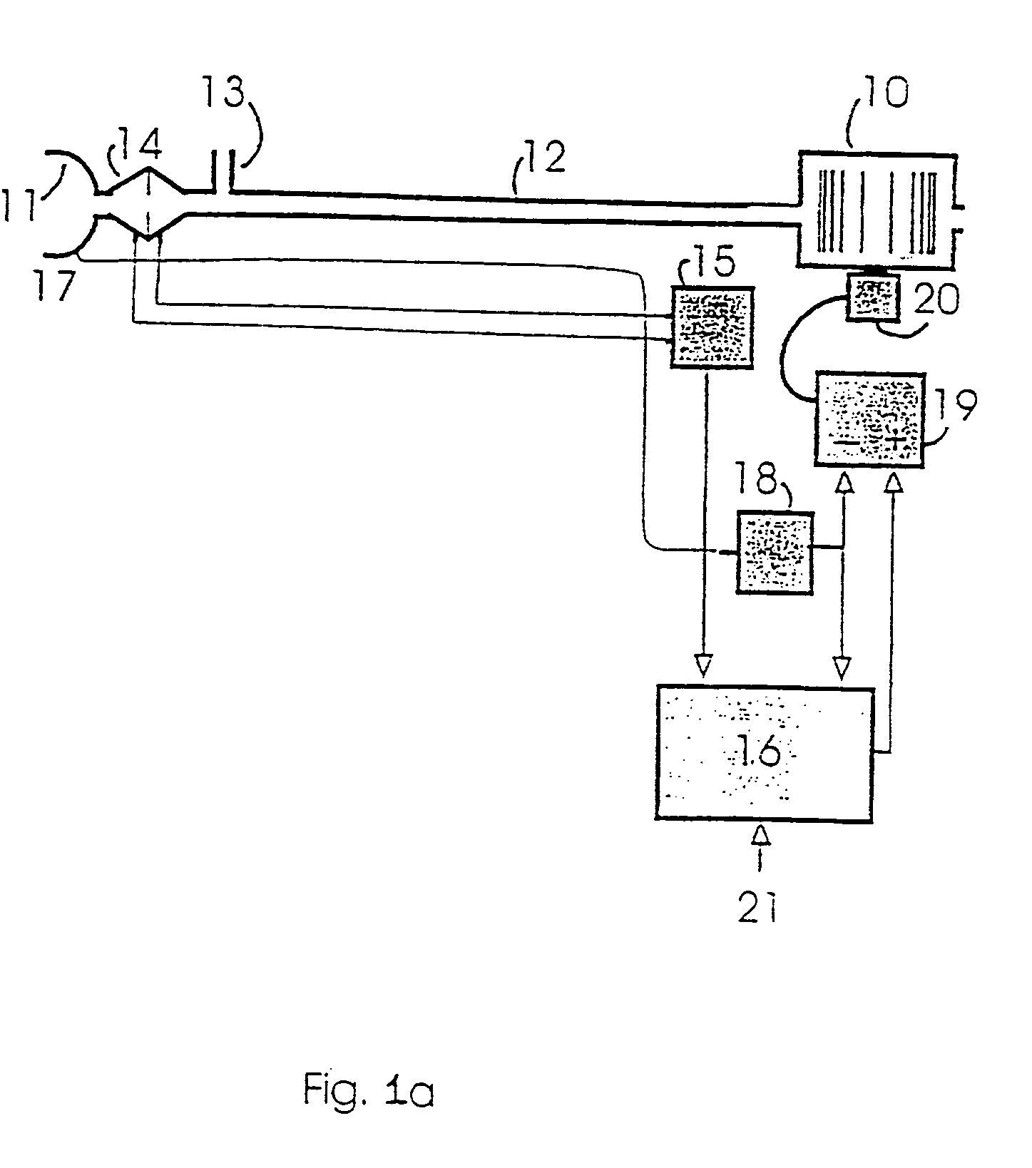
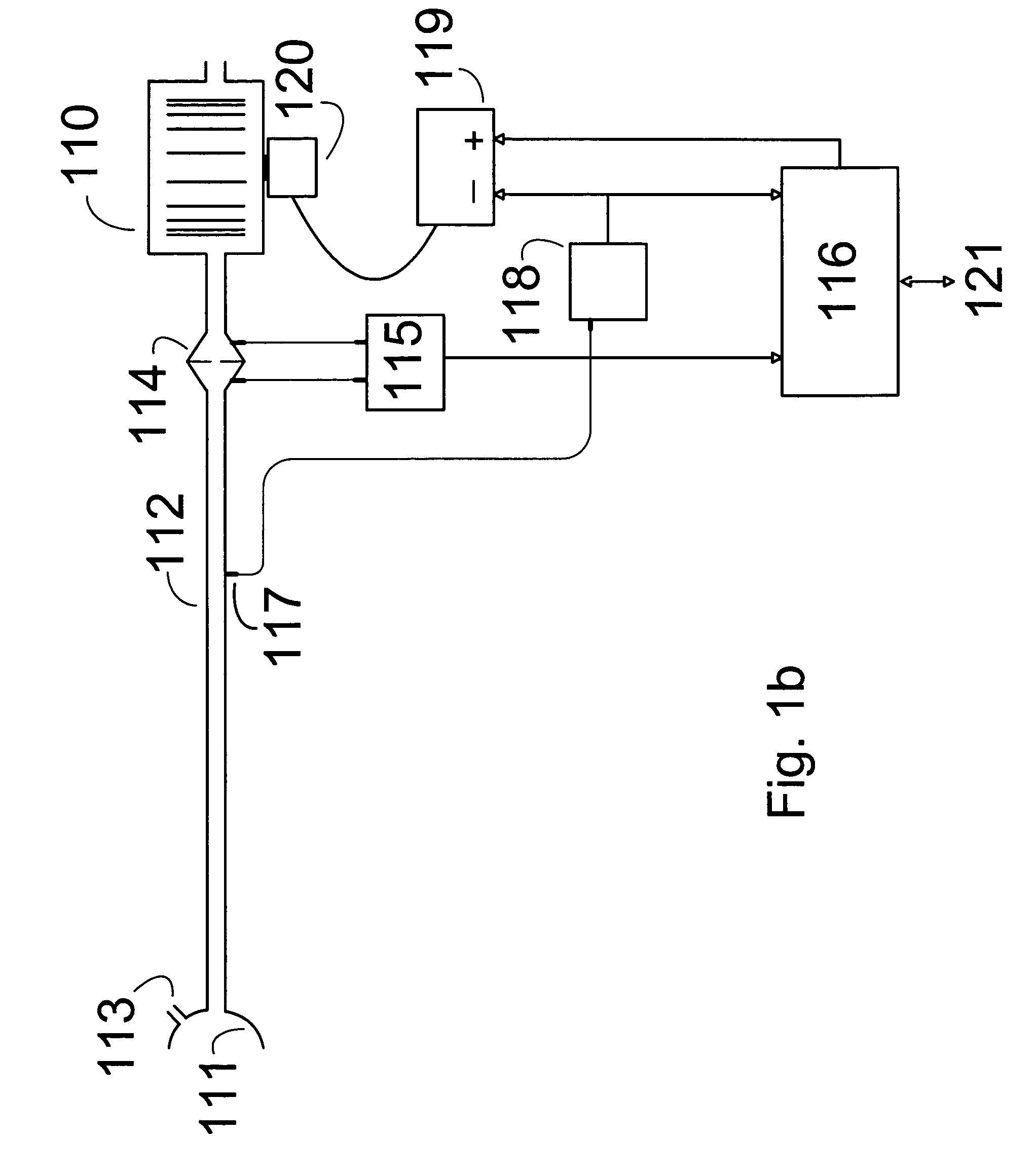
[0132]Apparatus to give effect to a first embodiment of the apparatus is shown in FIG. 1a. A blower 10 supplies a breathable gas to mask 11 in communication with the subject's airway via a delivery tube 12 and exhausted via a exhaust diffuser 13. Airflow to the mask 11 is measured using a pneumotachograph 14 and a differential pressure transducer 15. The mask flow signal from the transducer is then sampled by a microprocessor 16. Mask pressure is measured at the port 17 using a pressure transducer 18. The pressure signal from the transducer 18 is then sampled by the microprocessor 16. The microprocessor 16 sends an instantaneous mask pressure request signal to the servo 19, which compares said pressure request signal with actual pressure signal from the transducer 18 to the control fan motor 20. The processor settings can be adjusted via a serial port 21.

[0133]It is to be understood that the mask could equally be replaced with a tracheotomy tube, endotracheal tube, nasal pillows, or...


PUM


Abstract

The apparatus provides for the determination of the instantaneous phase in the respiratory cycle, subject's average respiration rate and the provision of ventilatory assistance. A microprocessor (16) receives an airflow signal from a pressure transducer (18) coupled to a port (17) at a mask (11). The microprocessor (16) controls a servo (19), that in turn controls the fan motor (20) and thus the pressure of air delivered by the blower (10). The blower (10) is coupled to a subject's mask (ii) by a conduit (12). The invention seeks to address the following goals: while the subject is awake and making substantial efforts the delivered assistance should be closely matched in phase with the subject's efforts; the machine should automatically adjust the degree of assistance to maintain at least a specified minimum ventilation without relying on the integrity of the subject's chemoreflexes; and it should continue to work correctly in the presence of large leaks.

Description

[0001]This application is a continuation of U.S. patent application Ser. No. 10 / 188,489, filed Jul. 3, 2002 now U.S. Pat. No. 6,810,876, which is a continuation of U.S. patent application Ser. No. 09 / 549,197, filed on Apr. 13, 2000, now U.S. Pat. No. 6,484,719, which is a continuation of U.S. patent application Ser. No. 08 / 935,785, filed on Sep. 23, 1997, now U.S. Pat. No. 6,532,957.FIELD OF THE INVENTION[0002]The invention relates to methods and apparatus for the provision of ventilatory assistance matched to a subject's respiratory need. The ventilatory assistance can be for a subject who is either spontaneously or non-spontaneously breathing, or moves between these breathing states. The invention is especially suitable for, but not limited to, spontaneously breathing human subjects requiring longterm ventilatory assistance, particularly during sleep.BACKGROUND OF THE INVENTION[0003]Subjects with severe lung disease, chest wall disease, neuromuscular disease, or diseases of respir...

Claims


Application Information

Patent Timeline
Patent Type & Authority Patents(United States)
IPC IPC(8): A61M16/00A61B5/08A61B5/085A61B5/087
CPCA61B5/085A61B5/087A61M16/00A61M16/0051A61M16/0069A61M16/0003A61M16/06A61M2016/0021A61M2016/0036A61M2205/15A61M2016/0027A61B5/7264A61M16/1055A61M16/107A61M16/024G16H50/20
Inventor BERTHON-JONES, MICHAEL
Owner RESMED LTD
Learn More