
Trip indicator and electrical switching apparatus employing the same

a technology of circuit breakers and indicators, which is applied in the direction of circuit breakers, circuit breakers for excess current, circuit breakers, etc., can solve the problems of difficult to quickly visualize the status of such circuit breakers, not always the case, and more pronounced problems

Active Publication Date: 2006-11-14
EATON INTELLIGENT POWER LTD
View PDF13 Cites 15 Cited by
  • Summary
  • Abstract
  • Description
  • Claims
  • Application Information

AI Technical Summary

Benefits of technology

The present invention is a circuit breaker with a trip indicator that can be easily viewed to determine if the circuit breaker has tripped. The trip indicator is a movable member that is connected to the operating mechanism of the circuit breaker and can be depressed to lock the operating handle. The trip indicator is designed to prevent accidental or arbitrary resetting of the circuit breaker. The technical effects of the invention include improved safety and reliability, as well as more efficient and effective maintenance and repair of the circuit breaker.

Problems solved by technology

However, this is not always the case.
It is difficult to quickly visually determine the status of such circuit breakers.
This is problematic and it is even more pronounced when the circuit breaker is only one of a plurality of circuit breakers arranged within the same panelboard or switchboard perhaps with several breakers already intentionally turned OFF.
Under such circumstances, it is nearly impossible to determine which circuit breakers have tripped because the operating handle appears in the same position as it does for the breakers which have been intentionally turned OFF.
However, the trip indicia of such indicators are somewhat concealed within the opening in the circuit breaker housing and often can only be clearly seen when viewed from a very close range and substantially straight on through the lens or glass window.
This is disadvantageous because, in most circuit breaker applications, many of the circuit breakers are located or positioned at an elevation other than at eye level, thus limiting the effectiveness of the indictor.
This is undesirable under certain circumstances where it is advantageous to prevent the breaker from being arbitrarily reset.
Otherwise, the breaker might continue to trip or damage could occur to electrical equipment in communication with the circuit breaker.

Method used


Image

  • Trip indicator and electrical switching apparatus employing the same
  • Trip indicator and electrical switching apparatus employing the same
  • Trip indicator and electrical switching apparatus employing the same

Examples


Embodiment Construction

[0028]For purposes of illustration, the invention will be described as applied to the trip indicator of a circuit breaker, although it will become apparent that it could also be applied to other types of electrical switching apparatus (e.g., without limitation, circuit switching devices and other circuit interrupters, such as, for example, contactors, motor starters, motor controllers and other load controllers) having an operating mechanism with a tripped position.

[0029]As employed herein, the term “fastener” refers to any suitable connecting or tightening mechanism expressly including, but not limited to, screws, bolts and the combinations of bolts and nuts (e.g. without limitation, lock nuts) and bolts, washers and nuts.

[0030]As employed herein, the statement that two or more parts are “coupled” together shall mean that the parts are joined together either directly or joined through one or more intermediate parts.

[0031]As employed herein, the term “trip condition” refers to any a...


PUM


Abstract

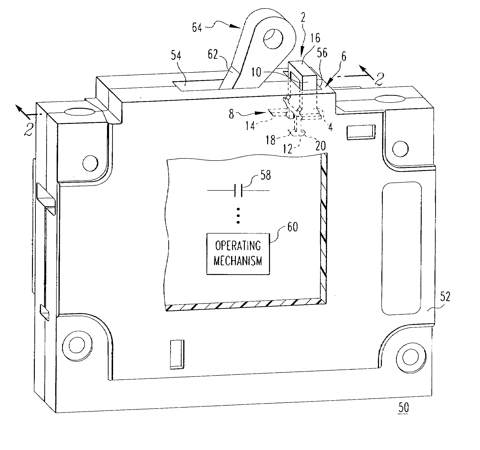
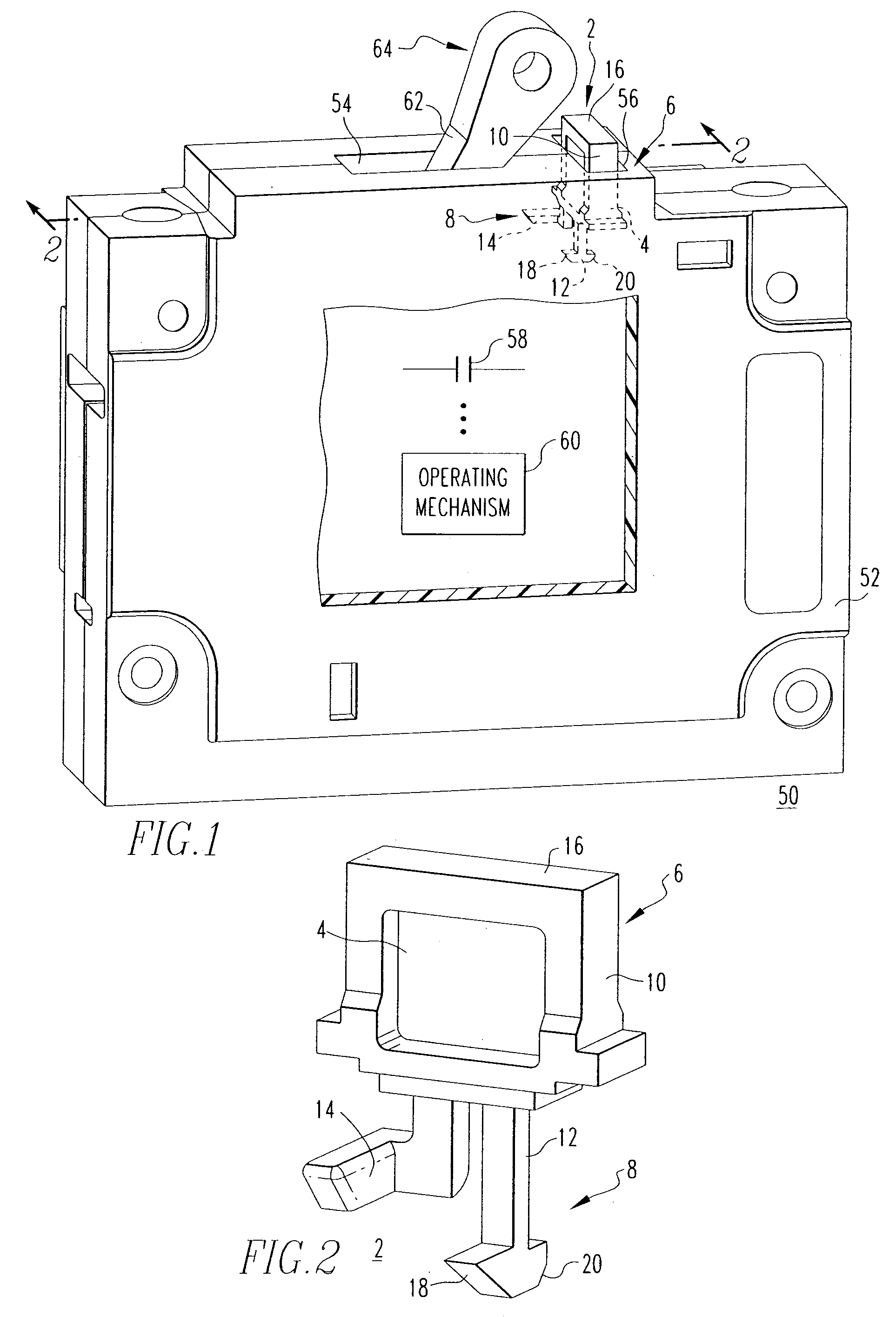
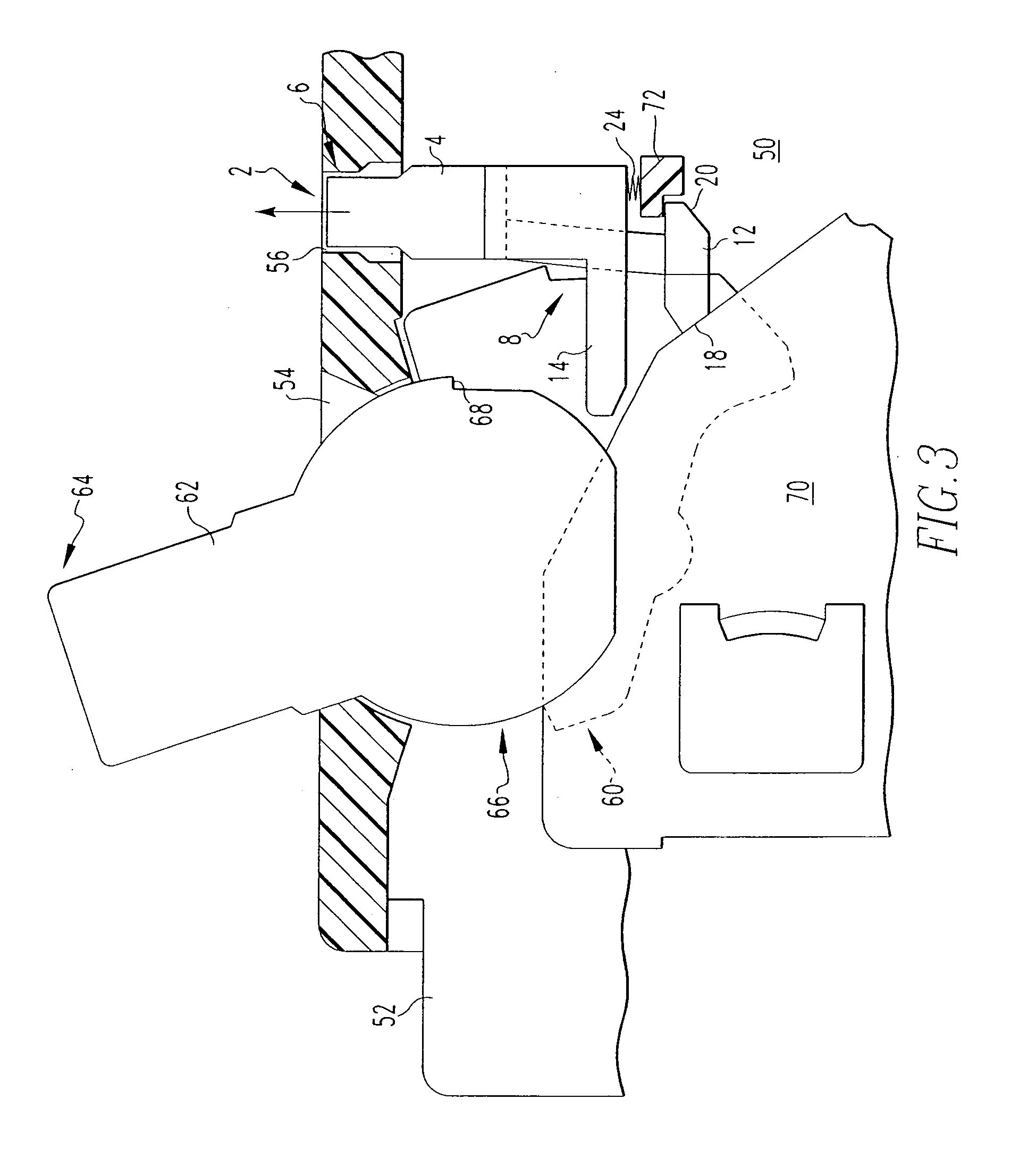
A trip indicator is for a circuit breaker having a housing including first and second openings, separable contacts and an operating mechanism having an operating handle for opening and closing the separable contacts. The trip indicator includes a trip indicating member with a first end having a trip indicia and a second end with first and second projections. The first projection is engaged by a cradle of the operating mechanism when the separable contacts are not tripped, in order to prevent the trip indicia from being viewable at the second opening of housing. The first projection is disengaged and released when the separable contacts trip, causing the trip indicating member to move in order that the trip indicia is viewable at the second opening. A locking feature in which the second projection engages and locks operating handle, is also disclosed.

Description

BACKGROUND OF THE INVENTION[0001]1. Field of the Invention[0002]The present invention relates generally to electrical switching apparatus and, more particularly, to a trip indicator for a circuit breaker. The invention also relates to circuit breakers including a trip indicator.[0003]2. Background Information[0004]Circuit breakers are generally old and well known in the art. Examples of circuit breakers are disclosed in U.S. Pat. Nos. 5,341,191 and 5,471,184. Circuit breakers are used to protect electrical circuitry from damage due to a trip condition, such as, for example, an overcurrent condition, an overload condition, an undervoltage condition, or a relatively high level short circuit or fault condition. Molded case circuit breakers, for example, include at least one pair of separable contacts which are operated either manually by way of a handle disposed on the outside of the case, or automatically by way of a trip unit in response to the trip condition.[0005]Circuit breakers t...

Claims


Application Information

Patent Timeline
Patent Type & Authority Patents(United States)
IPC IPC(8): H01H73/12
CPCH01H71/04
Inventor WHIPPLE, MICHAEL J.LIAS, EDWARD E.GIBSON, JEFF S.
Owner EATON INTELLIGENT POWER LTD
Learn More