
Simplified inductive position sensor and circuit configuration

a technology of applied in the field of simplified inductive position sensor and circuit configuration, can solve the problems of higher cost and labor than design, and achieve the effect of reducing errors and less sensitivity to changes

Active Publication Date: 2006-11-14
NYCE DAVID SCOTT
View PDF20 Cites 23 Cited by
  • Summary
  • Abstract
  • Description
  • Claims
  • Application Information

AI Technical Summary

Benefits of technology

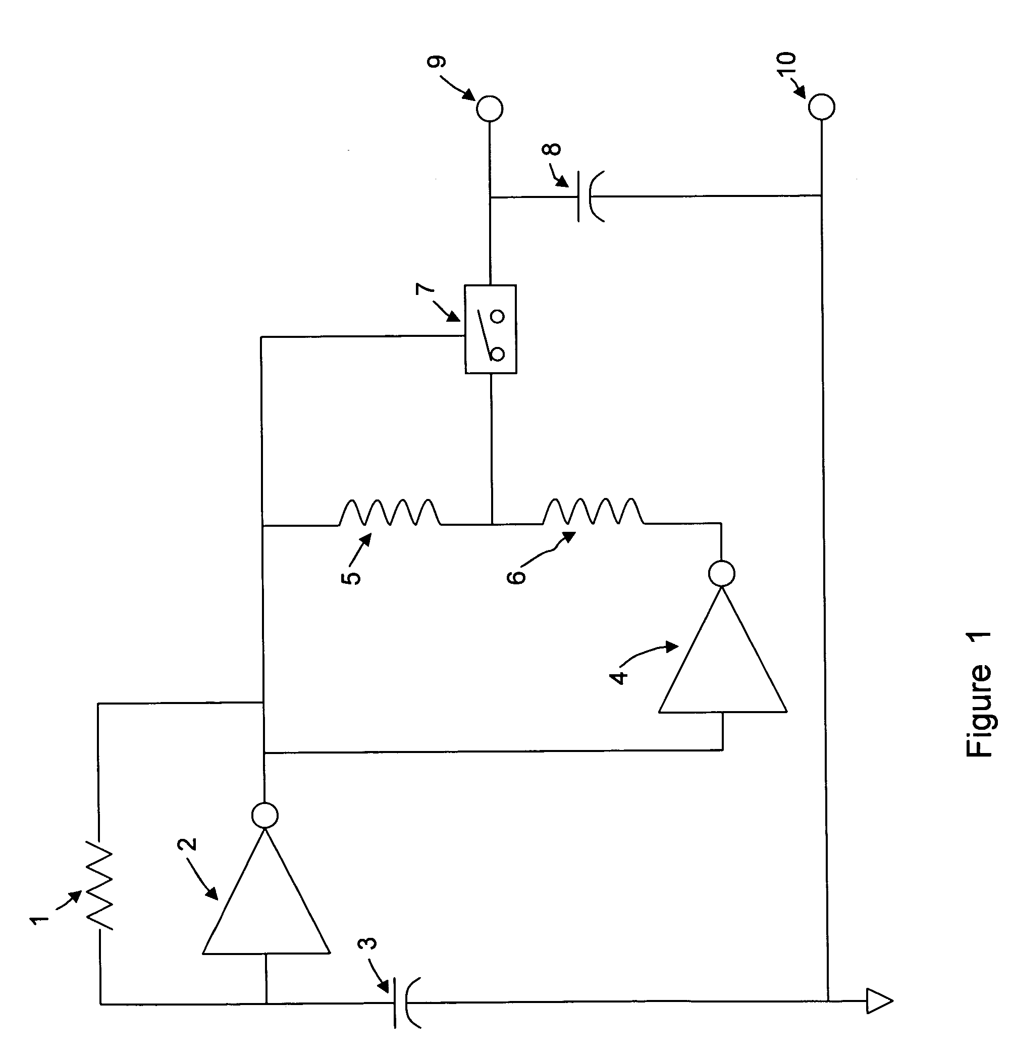
"The present invention provides a novel method for measuring position using a simple flat structure of conductors and an inexpensive electronic circuit. This method avoids problems associated with interconnecting more than one set of planar coils and the cost of complicated circuitry normally used to produce a transducer electrical output. The sensor and circuits of the present invention are easily configurable to support linear, rotary, or curved path position measurement. The invention includes first and second conductor coils disposed on a stationary planar insulating member, with a movable member that is formed of an electrically conductive or magnetically permeable material that moves in the motion axis while maintaining parallel alignment with the stationary member. The first and second conductor coils form first and second impedances, which are affected by the movement of the movable member. The series connection of the impedances acts as a voltage divider, providing a variable AC voltage that is converted into a DC signal voltage that varies with the measurand. The invention also includes a two-part configuration of the movable member that reduces errors due to mechanical misalignment and cancel out temperature-induced errors."

Problems solved by technology

Using multiple planar circuit boards, and the required interconnections, also leads to higher cost and labor than designs according to the present invention.

Method used


Image

  • Simplified inductive position sensor and circuit configuration
  • Simplified inductive position sensor and circuit configuration
  • Simplified inductive position sensor and circuit configuration

Examples


Embodiment Construction

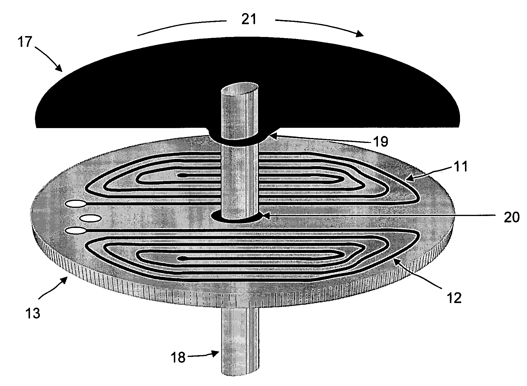
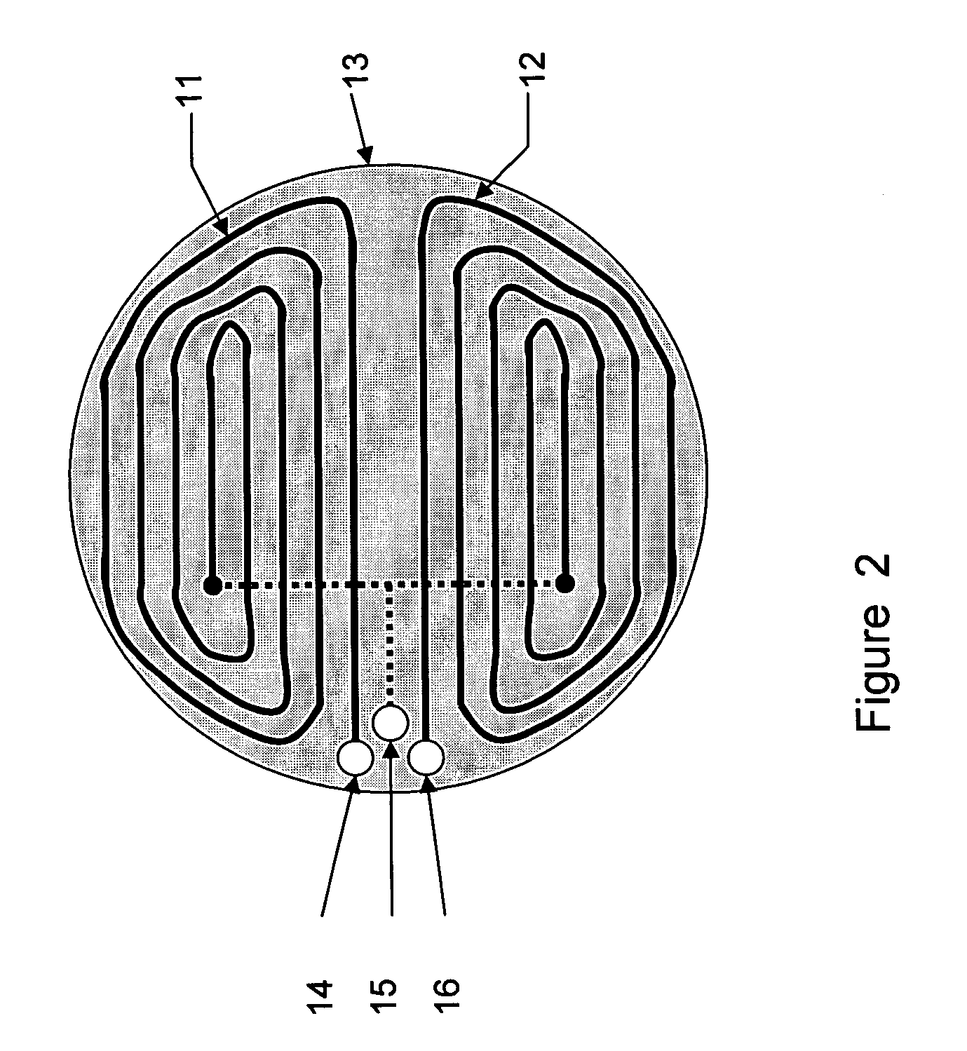
[0025]A first preferred embodiment of the present invention is shown in FIG. 3, and enables the measurement of rotary motion with the minimum of complexity in both the sensor and the associated electronic circuit. Together with the circuit of FIG. 1, a complete transducer can be constructed with a bare minimum of components, thus providing a simple and inexpensive transducer. As rotary movable member 17 moves along rotary motion axis 21, the impedance of coils 11 and 12 change in response to the measured position along motion axis 21. The movable member is fabricated from a ferromagnetic material, such as a nickel-iron alloy. Alternatively, it can be fabricated from an electrically conductive non-magnetic material, such as aluminum. With a ferromagnetic movable member, the coil impedance changes with position of the movable member due to the permeability of the ferromagnetic material, since the inductance and therefore the impedance of a coil varies approximately in direct proportio...


PUM

PropertyMeasurementUnit
frequenciesaaaaaaaaaa
angleaaaaaaaaaa
rotationaaaaaaaaaa

Abstract

Inductive position sensors and circuit configurations are disclosed for the measurement of linear, rotary, or curved position along a motion axis. The simplified sensor structures combine one or two parts of a movable core element with a simple planar substrate having first and second inductances connected in series. Movement of the core element in parallel to the planar substrate causing the impedance of at least one of the inductances to change. Simple circuit configurations are taught by which the impedance change is converted into a useful output signal that indicates position along the motion axis.

Description

BACKGROUND OF THE INVENTION[0001]1. Field of the Invention[0002]The present invention relates to sensors and transducers for the measurement of position. The measured position is typically that of a linear or rotary motion; alternatively, the motion may take the form of a curved path. The position measuring element, also called the primary sensor or the sensing element, is herein called the sensor. The sensor translates the measurand into a usable electrical signal called the sensor output. The present invention teaches a non-contact sensor comprising stationary and movable component parts, the measurement being the position of the movable part, called the movable element, with respect to the stationary part, called the stationary element. A driver circuit drives the sensor, and a signal conditioning circuit converts the sensor output into a standard electrical signal transducer output, such as zero to ten volts DC. An electronics module comprises the driver and signal conditioning ...

Claims


Application Information

Patent Timeline
Patent Type & Authority Patents(United States)
IPC IPC(8): G01B7/14H01F5/00G01B7/30G01D5/22
CPCG01D5/2216
Inventor NYCE, DAVID SCOTT
Owner NYCE DAVID SCOTT
Learn More