
Selective light attenuation system

a light attenuation system and selective technology, applied in the direction of roofs, superstructures, monocoque buildings, etc., can solve the problems of temporary blindness, blinding a driver, and dangerous intensity light sources

Active Publication Date: 2006-11-14
CONTINENTAL AUTOMOTIVE SYST INC
View PDF19 Cites 58 Cited by
  • Summary
  • Abstract
  • Description
  • Claims
  • Application Information

AI Technical Summary

Benefits of technology

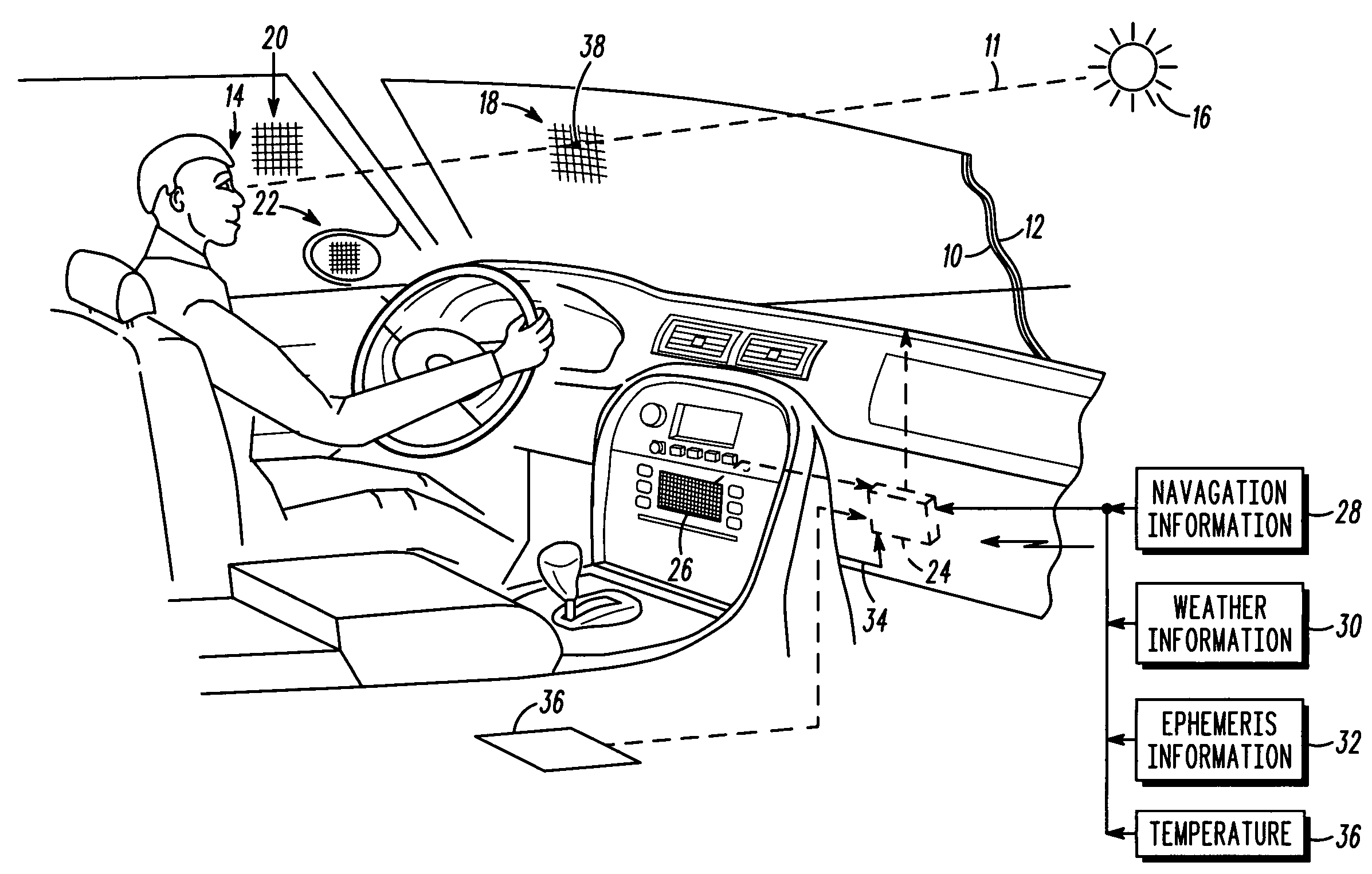
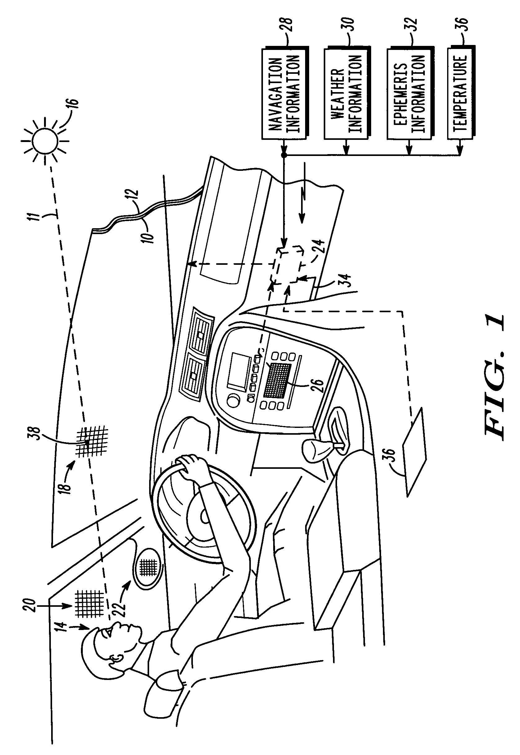
[0012]The present invention describes a system and method to selective attenuate intense light sources that do not require additional sensors and cameras, and do not require the tracking of a driver's eyes or position. The present invention can be applied to all vehicles, including land, sea, and aircraft. The present invention requires the addition of an electro-optic element that is disposed on one or more of the glass surfaces of the vehicle, along with associated control and processing devices. As a result, the present invention provides a system and method with a minimum amount of vehicle modifications, which reduces complexity, increases reliability and lowers costs.

Problems solved by technology

Vehicle operators are often exposed to intense light sources that can temporarily blind them while driving.
In addition, fixed sources of bright light, such as misdirected lighting at a factory and the like can also blind a driver.
These intense light sources are a safety hazard by posing a distraction while driving.
For example, the intense light may prevent drivers from seeing a possible hazard in their path.
Moreover, an intense light will probably require drivers to adjust their sun visor to block the light source, which reduces their attention to their driving.
Further, the sun visor itself will obstruct or lower a driver's visibility.
In addition, there are many times when the sun visor, due to its mechanical limitations, is ineffective in blocking light when the light source is in areas not covered by the visor.
However, complete tinting of a windshield is illegal, and is also impractical at night.
Moreover, the amount of tinting is limited by law, and therefore cannot provide sufficient protection from intense light sources such as the sun.
However, this solution has the disadvantage of being expensive, in that extra sensor and camera hardware is needed to not only detect the driver's (eye) position but also the light source position.
Moreover, the system requires extensive computational complexity to track not only the driver position but also the light source position, and then to calculate their geometry in relation to the filter and the coordinates of the specific pixels of the filter to activate in order to block the light from the source to the driver.
This solution has the same hardware problems of the previous case, and also requires even better tracking algorithms as the system must account for the movement of a driver's head.
As a result, this system must track the light source, driver, and spectacles, making the real-time computational requirements even more severe.
In addition, the wearing of these cumbersome spectacles would be a burden on the driver, making this solution impractical.
However, not only does this system have the same problems as the sun visor described above, it also has the disadvantage of extreme hardware additions and modifications, not to mention the extensive control logic requirements.
In addition, this system is prone to blockage of movement and mechanical breakdown.

Method used


Image

  • Selective light attenuation system
  • Selective light attenuation system
  • Selective light attenuation system

Examples


Embodiment Construction

[0012]The present invention describes a system and method to selective attenuate intense light sources that do not require additional sensors and cameras, and do not require the tracking of a driver's eyes or position. The present invention can be applied to all vehicles, including land, sea, and aircraft. The present invention requires the addition of an electro-optic element that is disposed on one or more of the glass surfaces of the vehicle, along with associated control and processing devices. As a result, the present invention provides a system and method with a minimum amount of vehicle modifications, which reduces complexity, increases reliability and lowers costs.

[0013]FIG. 1 demonstrates an application of the present invention in a vehicle, wherein the present invention selectively attenuates light 11 from a source of light 16 to a person's eyes 14 in a vehicle. A view from the driver's seat is shown looking out of the windshield. The source of light can be any intense lig...


PUM


Abstract

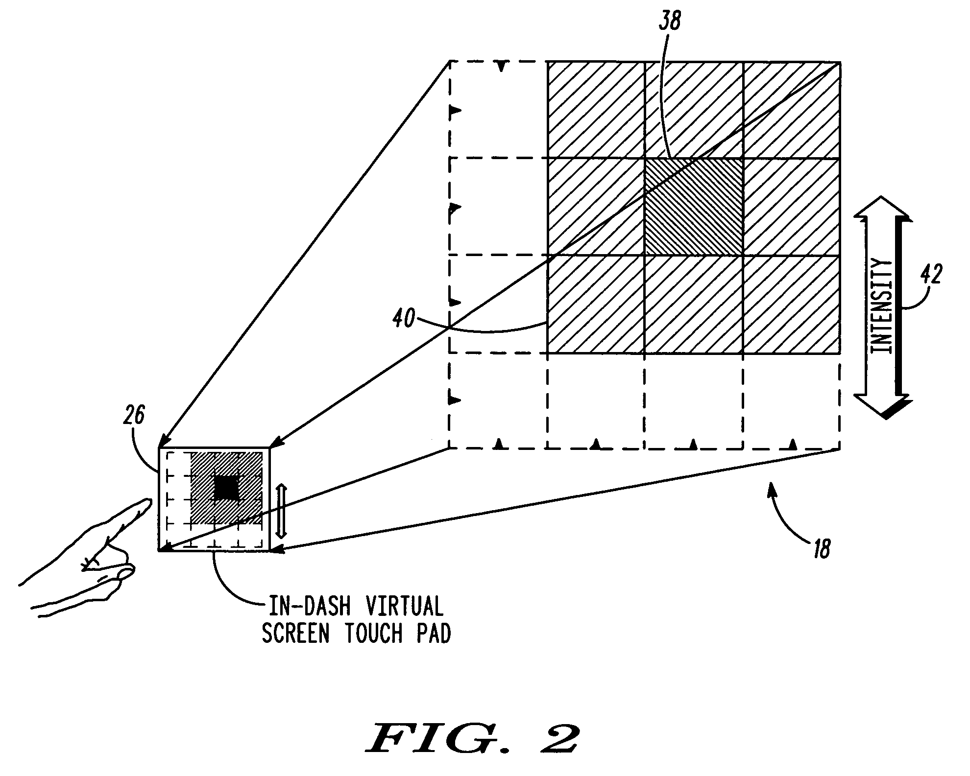
A system for selectively attenuating light from a source of light, such as the sun, to a person's eyes in a vehicle. The system includes an electro-optical element (10) interposed between the source of light (16) and the person's eyes (14). The element (10) has pixels (18) that are operable to individually attenuate (38) light passing therethrough. A navigation system (28) determines a location and direction of travel of the vehicle. A memory (24) contains a general location for the person's eyes within the vehicle. Information (32) is made available for determining a position of the source of light. A controller (24) operates to determine those pixels of the elements that are calculated (38) to be between the person's eyes and the source of light, and to reduce the light transmittivity of those pixels (38) to attenuate the light from the source (16) to the person's eyes (14).

Description

FIELD OF THE INVENTION[0001]The present invention is generally directed to the field of light transmission systems, and specifically for light transmission systems for attenuating light through a vehicle's windows.BACKGROUND OF THE DISCLOSURE[0002]Vehicle operators are often exposed to intense light sources that can temporarily blind them while driving. Such light sources can include the sun during the day and oncoming headlights at night, for example. In addition, fixed sources of bright light, such as misdirected lighting at a factory and the like can also blind a driver. These intense light sources are a safety hazard by posing a distraction while driving. For example, the intense light may prevent drivers from seeing a possible hazard in their path. Moreover, an intense light will probably require drivers to adjust their sun visor to block the light source, which reduces their attention to their driving. Further, the sun visor itself will obstruct or lower a driver's visibility....

Claims


Application Information

Patent Timeline
Patent Type & Authority Patents(United States)
IPC IPC(8): B60J3/00
CPCB60J3/04
Inventor ISAAC, EMAD S.
Owner CONTINENTAL AUTOMOTIVE SYST INC
Learn More