
Waiting tray for sheet processing tray

a technology of sheet processing and waiting tray, which is applied in the direction of electrographic process apparatus, thin material processing, instruments, etc., can solve the problem that the finisher cannot be as small as desired, and achieve the effect of time required and fast copying

Active Publication Date: 2006-11-14
TOSHIBA TEC KK
View PDF47 Cites 4 Cited by
  • Summary
  • Abstract
  • Description
  • Claims
  • Application Information

AI Technical Summary

Benefits of technology

[0009]An object of the present invention is to provide a sheet post-process apparatus that serves to shorten the time required for fast copying.
[0014]The post-process apparatus has the third storage tray that holds sheets ejected without being conveyed to the waiting tray or the processing tray. The path through which these sheets are conveyed to the third storage tray is short. The end-user of the apparatus need not wait long to obtain the sheets. The apparatus can shorten, in particular, the time required for fast copying.

Problems solved by technology

Having a long sheet-conveying path, the finisher cannot be as small as desired.

Method used


Image

  • Waiting tray for sheet processing tray
  • Waiting tray for sheet processing tray
  • Waiting tray for sheet processing tray

Examples


Embodiment Construction

[0033]An embodiment of this invention will be described, with reference to the accompanying drawings.

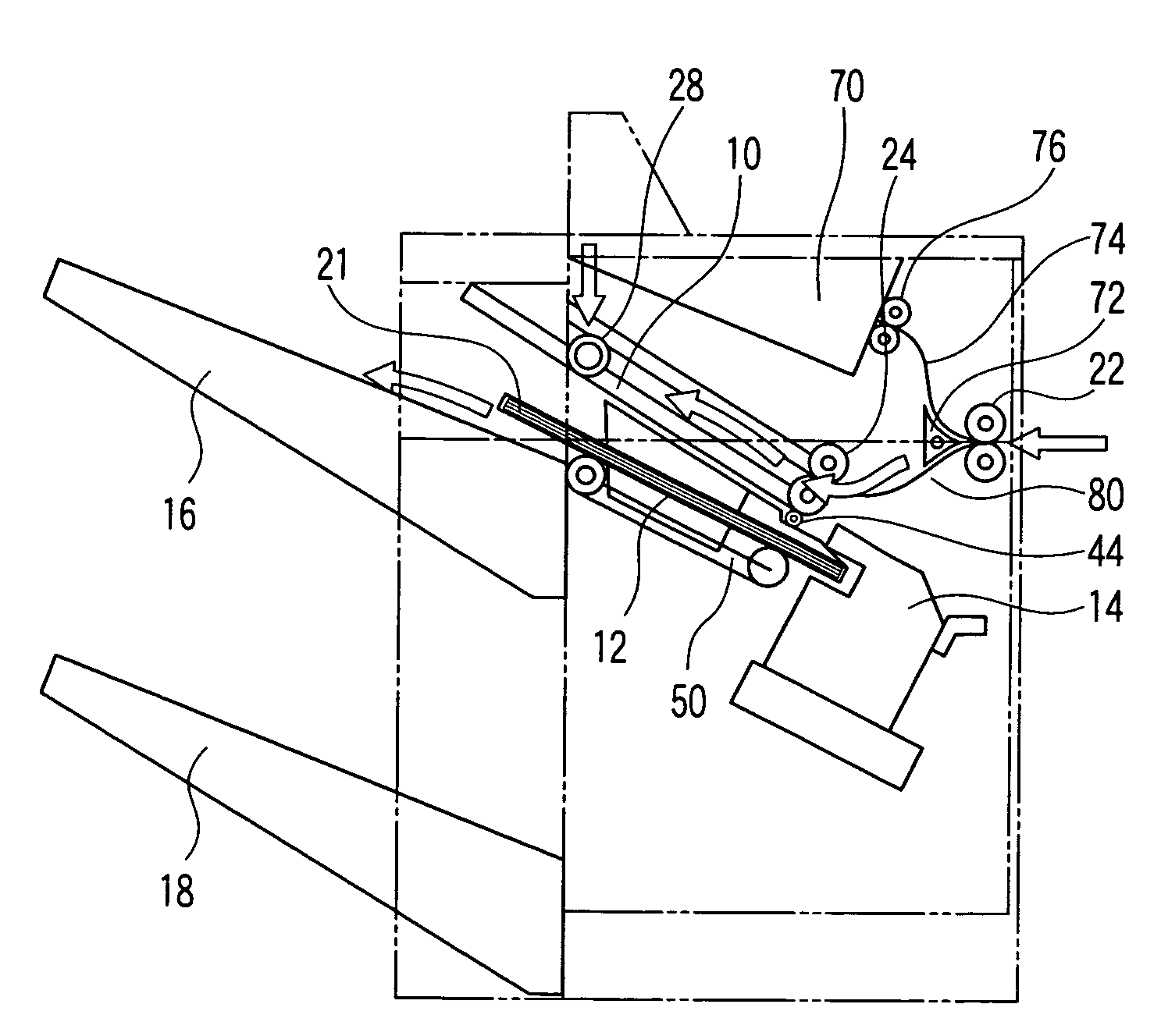
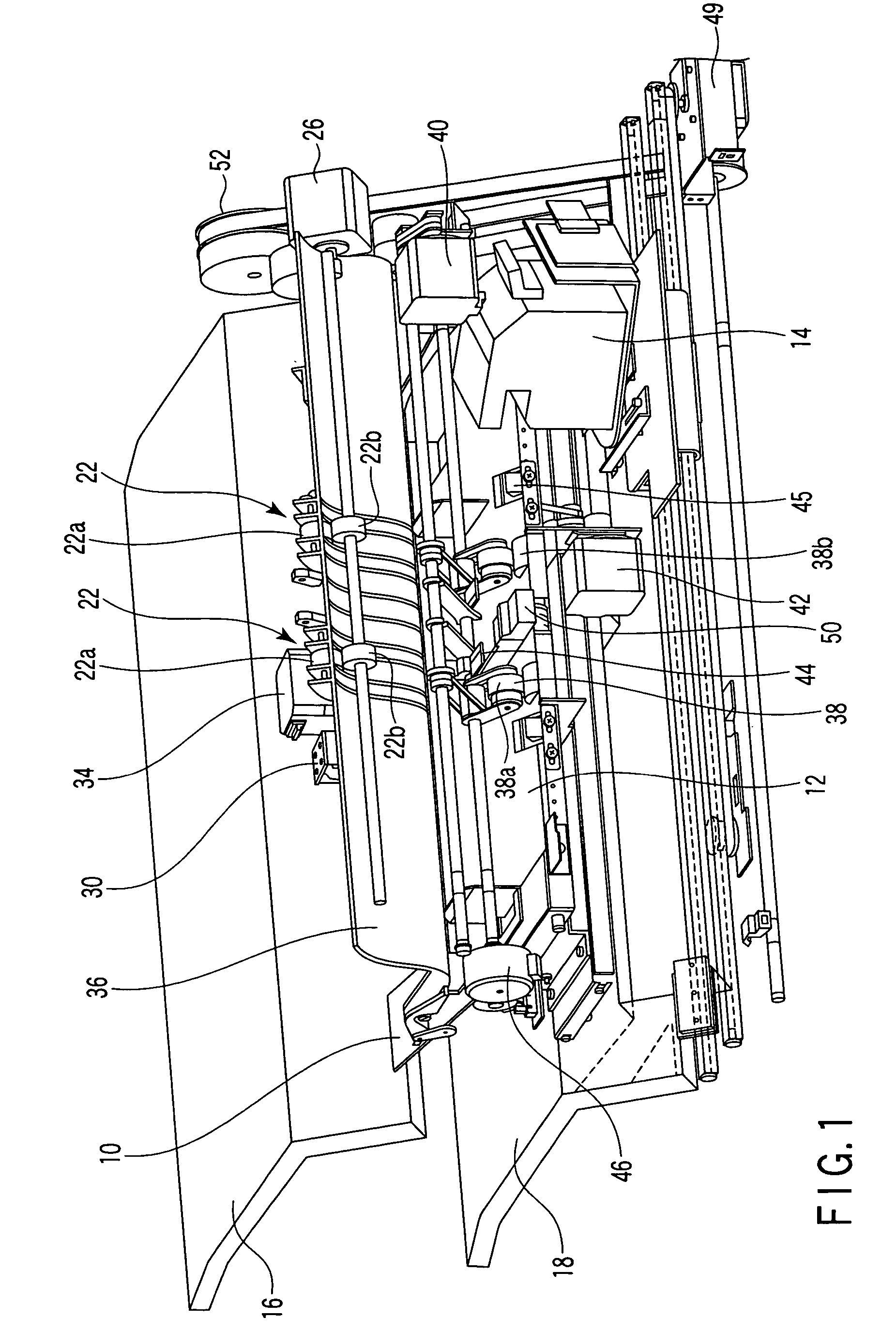
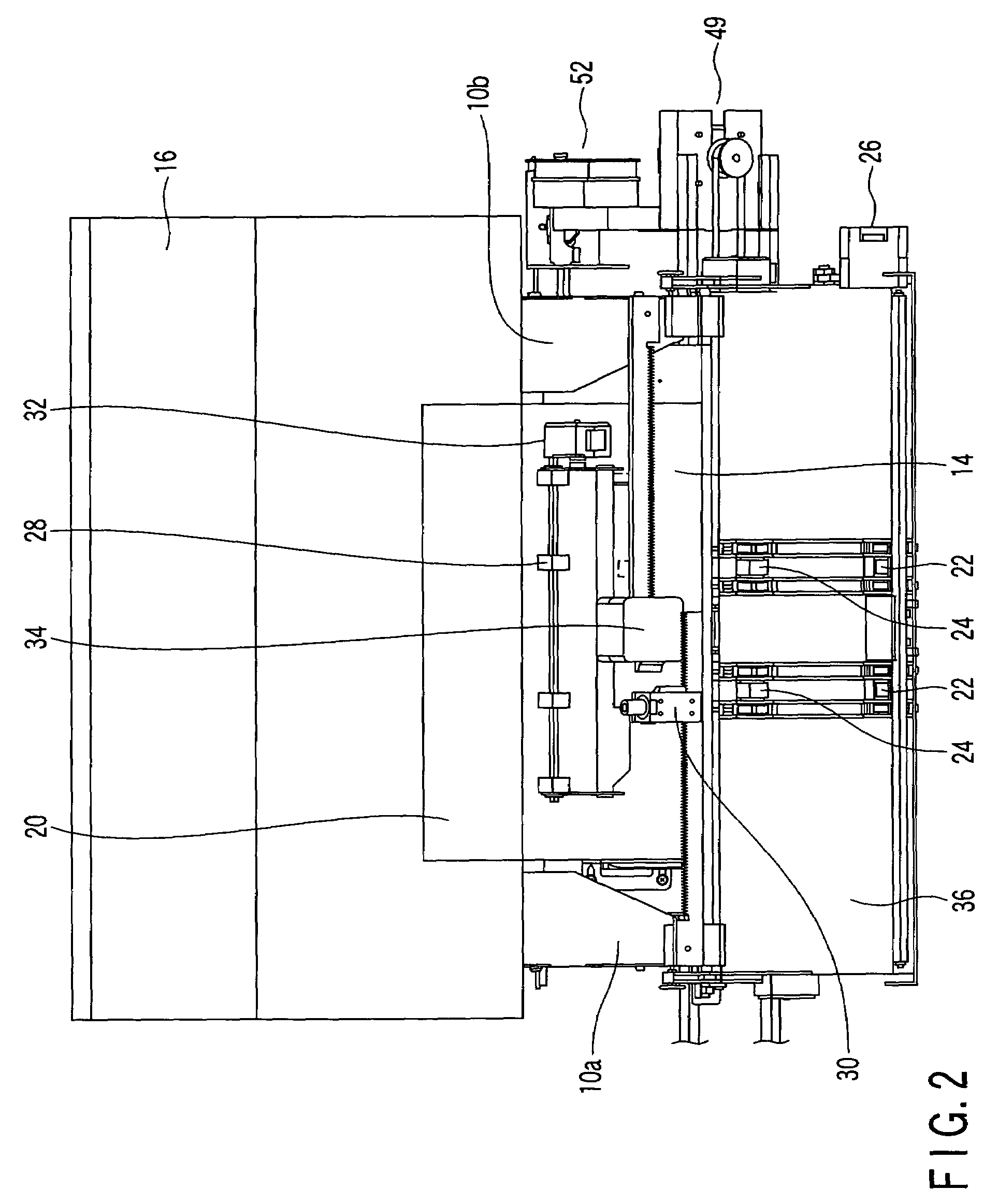
[0034]FIG. 1 is a perspective view of a section of a sheet post-process apparatus according to this invention. FIG. 2 is a top view of said section of the post-process apparatus. As FIG. 1 shows, the post-process apparatus comprises a waiting tray 10, a processing tray 12, a stapler 14, a first storage tray 16, and a second storage tray 18.

[0035]The sheet post-process apparatus further comprises a pair of input rollers 22, a pair of sheet-feeding rollers 24, and an input-roller motor 26. The input rollers 22 receive a sheet 20 supplied from an MFP and convey the sheet 20 to the sheet-feeding rollers 24. The sheet-feeding rollers 24 convey the sheet 20 to the waiting tray 10. The input-roller motor 26 drives the input rollers 22.

[0036]One of the input rollers 22 is an upper input roller 22a, and the other input roller 22 is a lower input roller 22b. Likewise, one of the sheet-feeding ...


PUM


Abstract

A waiting tray is provided in a sheet-conveying path and holds sheets if the sheets need to be post-processed. A processing tray receives sheets conveyed from the waiting tray. It may receive sheets conveyed through the sheet-conveying path and coming not via the waiting tray, before the sheets are post-processed. A conveying mechanism is provided, which causes the sheets to fall, due to gravity, from the waiting tray onto a processing tray. A sheet-aligning mechanism aligns the sheets on the processing tray, at their transverse edges and longitudinal edges. On the processing tray, the sheets are post-processed, forming a bundle. A third storage tray holds the sheets ejected without being conveyed to the waiting tray or the processing tray.

Description

CROSS-REFERENCE TO RELATED APPLICATIONS[0001]This application is based upon and claims the benefit of priority from prior Japanese Patent Application No. 2004-282210, filed Sep. 28, 2004, the entire contents of which are incorporated herein by reference.BACKGROUND OF THE INVENTION[0002]1. Field of the Invention[0003]The present invention relates to a sheet post-process apparatus, such as a finisher, which is designed for installation at the outlet side of a multi-function periperal (MFP).[0004]2. Description of the Related Art[0005]An apparatus called “finisher” is known, which receives printed sheets supplied from an MFP and staples them together. In the finisher, the sheets supplied from the MFP are sequentially conveyed to a tray and stapled by a stapler, forming a bundle of sheets. The bundle of sheets is ejected from the apparatus onto a storage tray.[0006]Jpn. Pat. Appln. KOKAI Publication No. 6-99070 discloses a finisher. This finisher performs a post-process on sheets. In th...

Claims


Application Information

Patent Timeline
Patent Type & Authority Patents(United States)
IPC IPC(8): B65H37/04
CPCB65H29/34B65H31/24B65H31/34B65H2801/27
Inventor TERAO, YASUNOBUTAKI, HIROYUKIYAMAMOTO, MIKIOYAMAMOTO, HAJIMESUGIZAKI, YOSHIAKI
Owner TOSHIBA TEC KK
Learn More