
Packaging system

a packaging system and packaging technology, applied in the field of packaging systems, can solve the problems of affecting the efficiency of the rotary vacuum packaging device, affecting the sealing properties of the packaged body, and excessive space inside the bags

Active Publication Date: 2006-11-14
FURUKAWA MFG
View PDF31 Cites 14 Cited by
  • Summary
  • Abstract
  • Description
  • Claims
  • Application Information

AI Technical Summary

Benefits of technology

The present invention is a system for packaging items into bags and then supplying them to a rotary vacuum packaging device. The system includes a beak-shaped hopper that moves back and forth to hold the mouths of the bags in a tense state during operation. The system also has means for detecting the resistance of the bag, identifying bag opening errors, and confirming the supply of bags. The invention allows for unmanned operation and ensures a tight vacuum seal of the bag. The technical effects of the invention include improved efficiency, accuracy, and reliability in the packaging process.

Problems solved by technology

However, with a vacuum packaging device of this kind, too, excessive space occurs inside the bags when packaged objects are of indefinite shapes.
However, a distortion or slack is caused to occur at the mouth of the bag during transportation, which impairs the vacuum sealing properties of the packaged body.
If such distortion or slack of the bag is removed while the bag is on the sealing platform, the efficiency of the rotary vacuum packaging device is adversely affected.

Method used


Image

  • Packaging system
  • Packaging system
  • Packaging system

Examples


Embodiment Construction

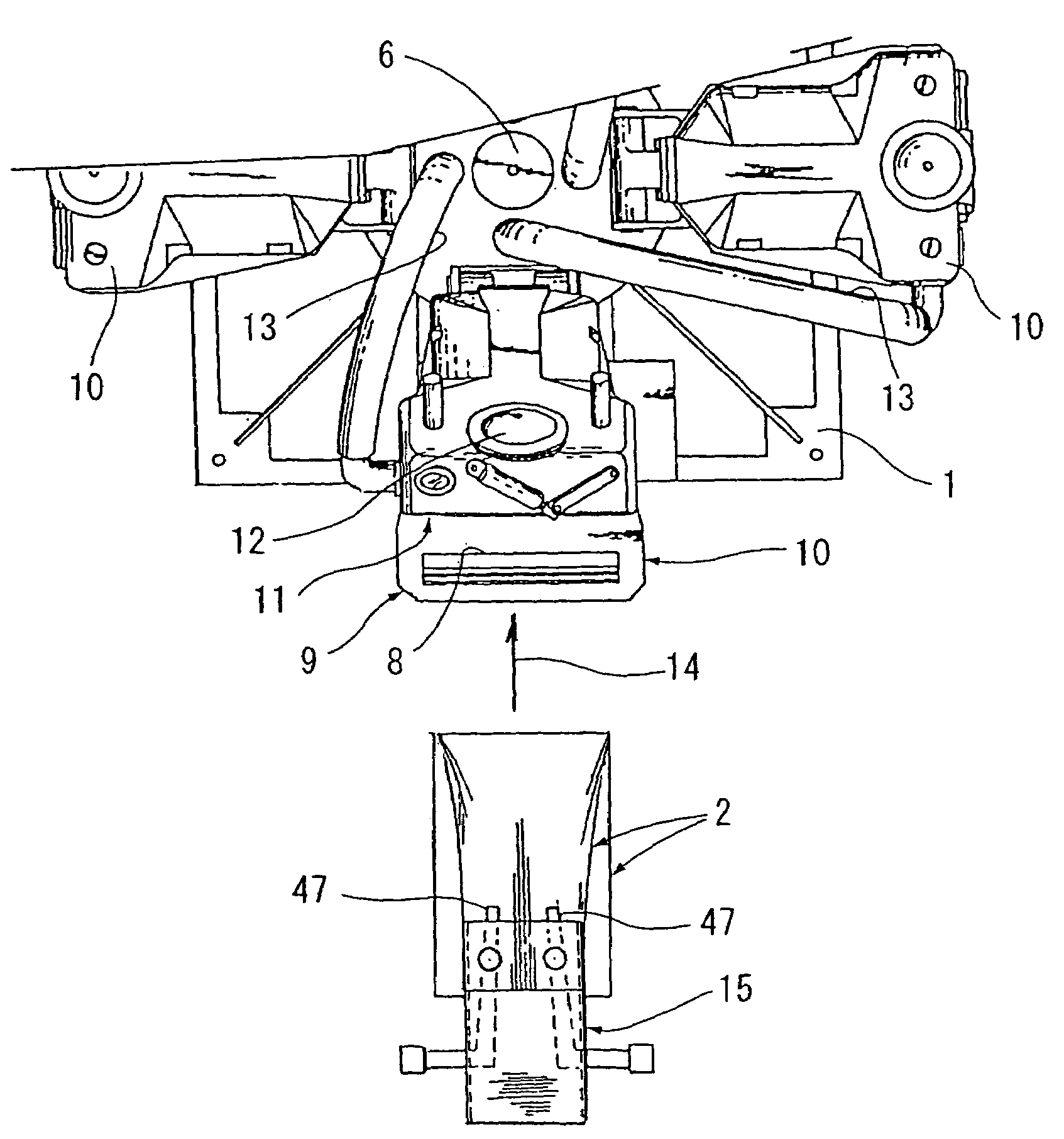
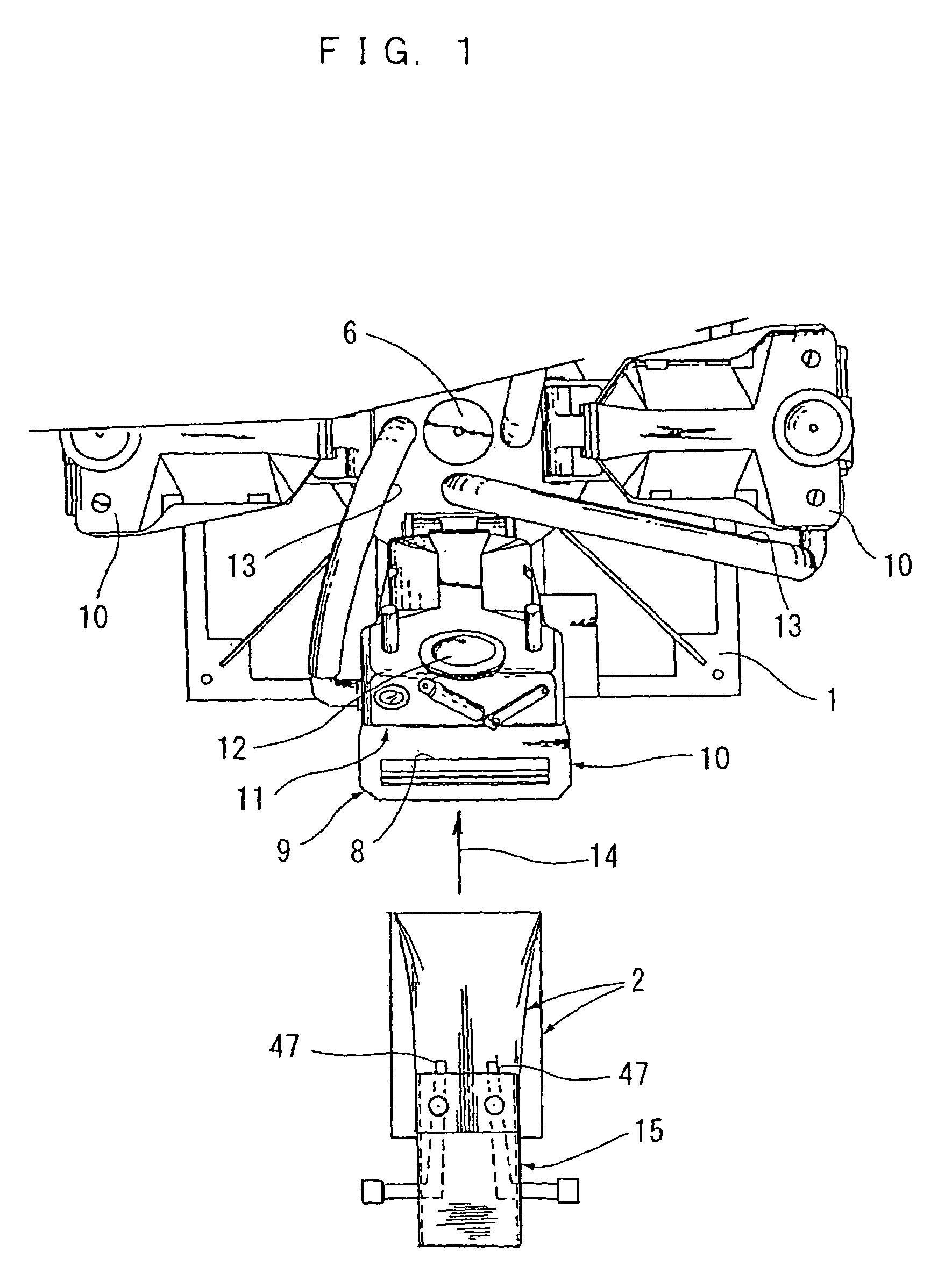
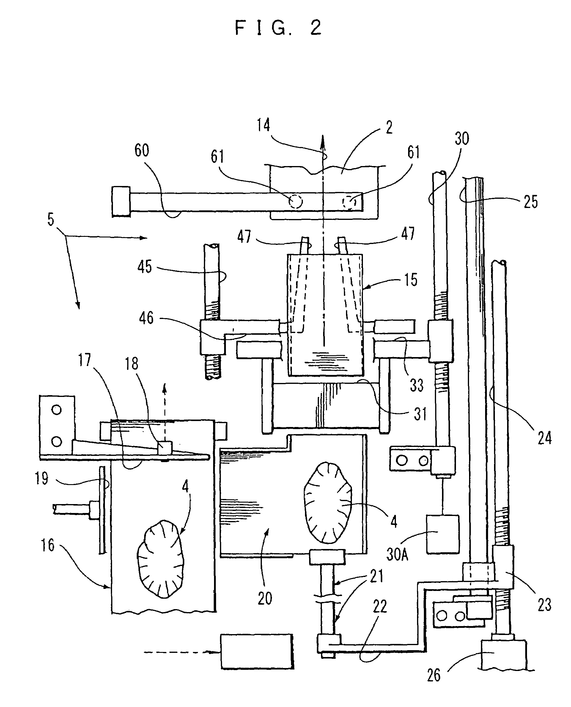
[0026]FIG. 1 is a partial plan view of a rotary vacuum packaging device, and FIG. 2 is a plan view of a device for supplying an item to be packaged and a bag, to the vacuum packaging device. The packaging system which is illustrated in a separated fashion in these two diagrams comprises a rotary vacuum packaging device 1 which seals a bag containing an item to be packaged, under vacuum conditions, thereby creating a vacuum packaged product, and respective conveyance mechanisms 5 for supplying empty bags to the vacuum packaging device 1 and accommodating the items to be packaged 4 inside the bags 2.

[0027]In FIG. 1, the rotary vacuum packaging device 1 is shown in a partial fashion, due to considerations of space, but this vacuum packaging device 1 comprises four pressure resistant chambers 10 which are rotated intermittently, at positions 90° apart, by means of the driving force of a centrally positioned main axle 6. The respective pressure resistant chambers 10 are each equipped wit...


PUM

PropertyMeasurementUnit
pressureaaaaaaaaaa
resistanceaaaaaaaaaa
air pressureaaaaaaaaaa

Abstract

The present invention provides a packaging system that includes a beak-shaped hopper, a pair of opening and closing bars, and a sensor for sensing a limitless opening and closing movement of the opening and closing bars. The beak-shaped hopper and the pair of opening and closing bars are operable to move in unison back and forth along a main travel path. The main travel path leads to a rotary vacuum packaging device having a pressure resistant chamber. The beak-shaped hopper is dimensioned to convey packaging bags into the pressure resistant chamber. The opening and closing bars are dimensioned to detect a bag on the hopper by opening towards both sides immediately after a bag has been conveyed into the pressure resistant chamber. A pushing bar is dimensioned to convey an item to be packaged into the bag when the bag is detected on the hopper by the opening and closing bars. The opening and closing bars contact a sensor for detecting movement of the opening and closing bars when a bag is not on the hopper.

Description

FIELD OF THE INVENTION[0001]The present invention relates to a packaging system for supplying bags for accommodating therein items to be packaged, to respective pressure resistant chambers provided with a rotary type vacuum packaging apparatus, in such a manner that they match the circulation pitch of the pressure resistant chambers.BACKGROUND OF THE INVENTION[0002]JP10-81310A describes a system in which a band-shaped film is formed into a tube-shape which surrounds the circumference of respective blocks of meat which move along a linear travel path, at equidistant intervals. The tube film into which a respective block of meat has been packaged is cut successively and separated, and each individual packaging bag containing a block of meat is supplied successively to a pressure resistant chamber of a rotary vacuum packaging device, by means of a belt conveyor. By means of this system, since a control is provided which causes the interval between the respective blocks of meat having a...

Claims


Application Information

Patent Timeline
Patent Type & Authority Patents(United States)
IPC IPC(8): B65B57/04B65B39/02B65B5/04B65B25/06B65B31/02B65B57/02
CPCB65B5/045B65B25/065B65B31/046B65B39/02B65B43/28B65B57/02
Inventor KUJUBU, EITAROKONDO, HIROSHIKUDO, WATARU
Owner FURUKAWA MFG
Learn More