
Network based diagnostic system and method for programmable hardware

a network-based, hardware-based technology, applied in the direction of pulse technique, instrumentation, program control, etc., can solve the problems of time-consuming user, difficult diagnostic and reconfiguration, and potentially expensive problems

Inactive Publication Date: 2006-11-07
XILINX INC
View PDF23 Cites 81 Cited by
  • Summary
  • Abstract
  • Description
  • Claims
  • Application Information

AI Technical Summary

Benefits of technology

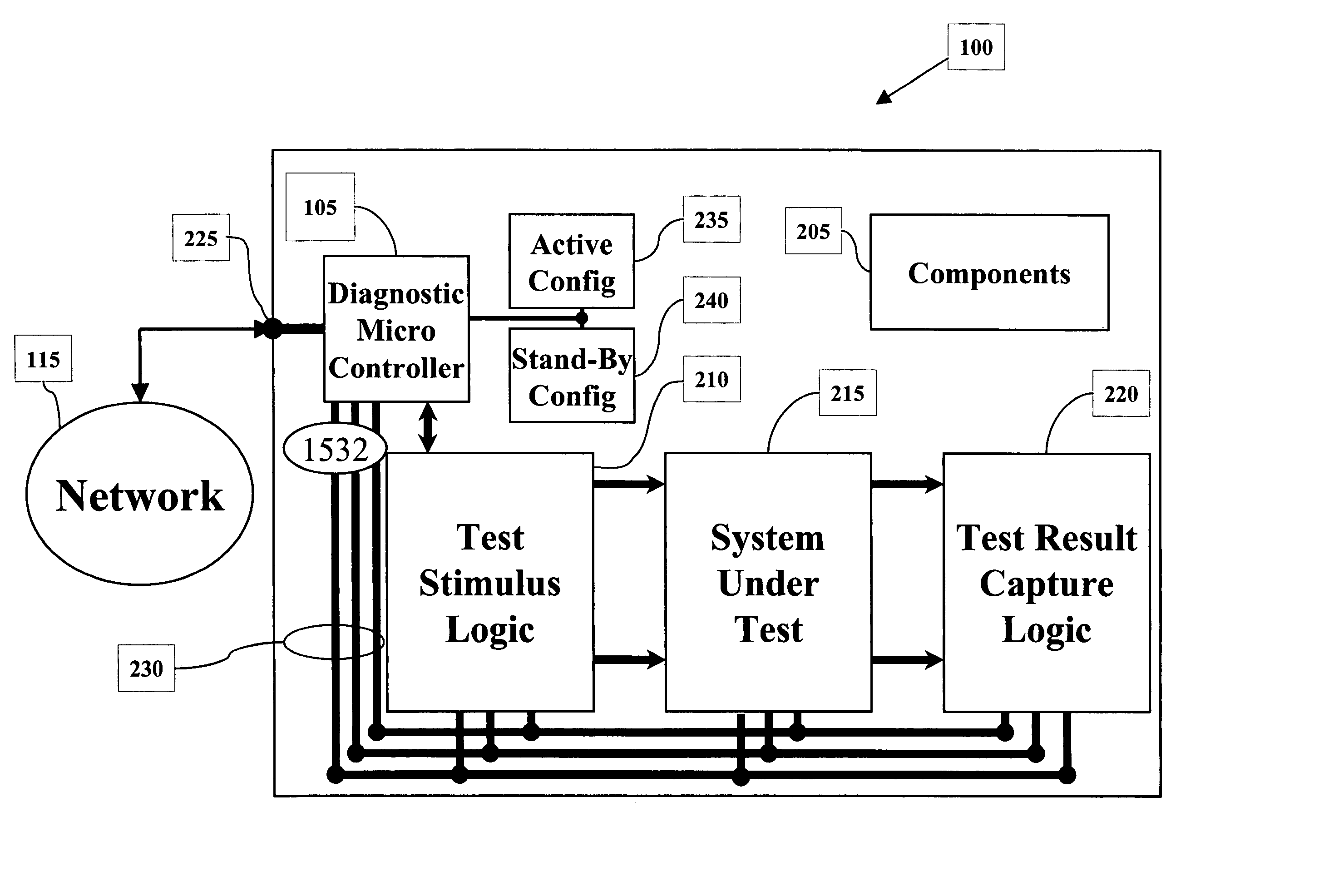
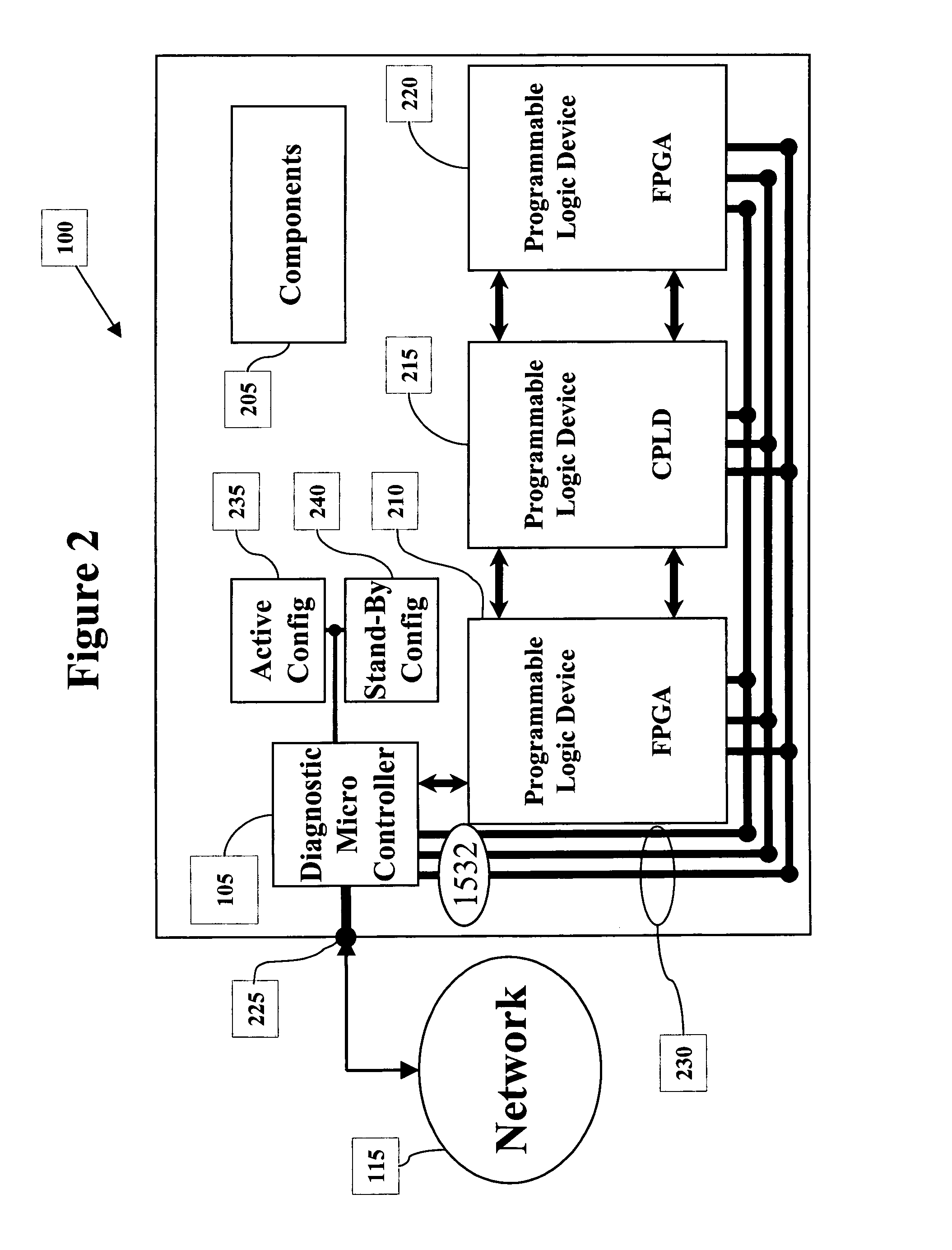
The present invention provides a diagnostic device for programmable logic devices embedded in electronic systems. The device includes an access controller and a diagnostic control module that communicates with the programmable logic device to perform diagnostic tests. The device can be controlled through a network and can have its programmable logic devices reconfigured based on the results of the diagnostic tests. The technical effects of the invention include the ability to remotely diagnose and reconfigure electronic devices installed in the field or in user's possession using a network.

Problems solved by technology

Although the PLDs are easily configured, it is difficult to diagnose and reconfigure them once they are embedded in the electronic device and in a user's possession.
This is time consuming for the user and potentially expensive.

Method used


Image

  • Network based diagnostic system and method for programmable hardware
  • Network based diagnostic system and method for programmable hardware
  • Network based diagnostic system and method for programmable hardware

Examples


Embodiment Construction

[0024]The following includes definitions of exemplary terms used throughout the disclosure. Both singular and plural forms of all terms fall within each meaning:

[0025]“Signals”, as used herein, includes but is not limited to one or more signals, a bit stream, an algorithm, a routine, a program or the like. The term “commands” is synonymous with “signals.”

[0026]“Software”, as used herein, includes but is not limited to one or more instructions, routines, algorithms, modules or programs including separate applications or from dynamically linked libraries for performing functions as described herein. Software may also be implemented in various forms such as a servlet, applet or other type of application.

[0027]“Logic”, as used herein, includes but is not limited to hardware, software and / or combinations of both to perform a function.

[0028]“Network”, as used herein, includes but is not limited to the internet, intranets, Wide Area Networks (WANs), Local Area Networks (LANs), and transduc...


PUM


Abstract

A system and method for diagnosing an electronic device remotely using a network is provided. The electronic device includes one or more programmable logic devices that are configurable. A diagnostic microcontroller functions to communicate to the programmable logic devices and to communicate to the network. To diagnose the electronic device, communication is established to the network and to a diagnostic / repair center. The diagnostic / repair center selects diagnostic commands and transmits them to the electronic device. The diagnostic microcontroller initiates the diagnostic commands on the one or more programmable logic devices to test their configuration and / or functionality. Test results are collected and transmitted back to the diagnostic / repair center for analysis. Based on the analysis, if appropriate, reconfiguration commands are sent to reconfigure the programmable logic device to correct identified errors.

Description

FIELD OF THE INVENTION[0001]The invention relates generally to diagnostic and repair systems. It will be appreciated that the invention finds particular application to a system and method for diagnosing and reconfiguring programmable logic devices within a remote electronic device over a network.BACKGROUND OF THE INVENTION[0002]A programmable logic device is a digital integrated circuit capable of being programmed after its manufacture to provide a variety of different logic functions. Examples include a programmable logic device (PLD) and a field programmable gate array (FPGA). A PLD generally includes ‘AND’ gates, ‘OR’ gates, and Input / Output buffers, and functions differently depending on how it is programmed. An FPGA includes a gate array of logic elements (or macrocells), either gates or lookup table RAMs, flip-flops and programmable interconnect wiring. Typical FPGAs are reprogrammable since their logic functions and interconnects are defined by RAM cells. While a typical PLD ...

Claims


Application Information

Patent Timeline
Patent Type & Authority Patents(United States)
IPC IPC(8): G06F9/455H03K17/693
CPCG06F11/2294G06F11/366
Inventor JACOBSON, NEIL G.
Owner XILINX INC
Learn More