
Camera

a technology for cameras and optical systems, applied in the field of cameras, can solve the problems of inability to use a relay optical system capable of providing sufficient light, the image on the image pickup device is subject to a problem, and the image pickup device having a wide image area is expensiv

Inactive Publication Date: 2006-11-07
MINOLTA CO LTD
View PDF17 Cites 38 Cited by
  • Summary
  • Abstract
  • Description
  • Claims
  • Application Information

AI Technical Summary

Benefits of technology

[0015]Another object of the present invention is to provide a construction that offers adequate exposure both in taking of a photograph and in picking up of an image in a camera capable of dividing an incident light beam for use both in taking a photograph on a silver salt film and in picking up an image on an image pickup device.
[0016]Still another object of the present invention is to provide a construction that allows previewing of picture effects achieved by changes in aperture or shutter speed in a camera capable of dividing an incident light beam for use in both photographing and observation of an image.
[0017]A further object of the present invention is to provide a construction in which an image is not darkened during previewing of picture effects achieved by changes in aperture or shutter speed in a camera capable of dividing an incident light beam for use in both photographing and observation of an image.
[0018]A still further object of the present invention is to provide a construction in which focus detection or the like is not hindered by the previewing of picture effects achieved by changes in aperture or shutter speed in a camera capable of dividing an incident light beam for use in both photographing and observation of an image.

Problems solved by technology

An attempt to simultaneously take a photograph on a silver salt film and pick up an image on an image pickup device is subject to a problem as described below.
Generally, an image pickup device having a considerably small image area is used for this purpose, since an image pickup device having a wide image area is expensive.
Considering an image pickup device of a ¼- to ½-inch type is generally used, the relay optical system needs to have a magnification of 1 / 10 to ¼. However, it is often impossible to use a relay optical system capable of supplying sufficient light, since there is only limited space for extra components inside a camera body.
As a consequence of the above limitations, the following problem arises.
This leads to that, although the exposure of a silver salt film can be adjusted by adjustment of aperture, the exposure of a image pickup device cannot be adjusted in the same manner; a different adjustment needs to be devised.
Moreover, if the aperture of the taking lens is adjusted to be narrower than F=5.6 when simultaneous taking of a photograph on a silver salt film is attempted during exclusively performed picking up of an image on an image pickup device, the amount of light incident on the image pickup device is also affected, disturbing proper picking up of an image.
Although a preview mechanism adopted conventionally in a single-lens reflex camera allows previewing of picture effects, an image provided by such a preview mechanism is dark, because the image is observed with the aperture stopped down.
Therefore, the conventional preview mechanism is defective because it does not offer a clear image when the aperture is extremely stopped down.
Moreover, if a camera is provided with a mechanism for detecting focus by use of a light beam incident through a taking lens, it is impossible to detect focus during previewing, because a light beam to be used for focus detection is obstructed when the aperture is extremely stopped down.
Further, since a conventional preview mechanism does not allow observation of a stationary image, it is difficult to preview an image photographed on a silver salt film, and it is impossible to observe picture effects (such as a shaken-image effect) achieved by a change in shutter speed.
S63-284527 allows previewing of an image frame, it does not allow previewing of picture effects achieved by changes in aperture or shutter speed.

Method used


Image

  • Camera
  • Camera
  • Camera

Examples


first embodiment

[0283]As shown in FIG. 24, this embodiment uses a relay optical system of a magnification β=⅛, a relay aperture diaphragm of an open aperture value F=2.0 (also referred to as a), and a taking lens of an open aperture value F=4.0, among which the taking lens is the same as that used in the As shown in the figure, a light beam from the taking lens TL enters the relay optical system RL without diffusing on the primary image plane IMG1. Accordingly, of the light beam incident from the taking lens TL, only a portion corresponding to a / β=16.0, that is, F=16.0 is used as a light beam which passes through the relay optical system RL to form a secondary image IMG2, while the remaining light beam (indicated with hatching in the drawing) passing outside the light beam corresponding to F=16.0 does not enter the image pickup device. As a result, if the aperture is adjusted to be wider than F=16.0, the amount of light incident on the film F accordingly changes, without affecting the imaging on t...

fifth embodiment

[0422]Hereinafter, the present invention will be described. The external views of this embodiment are the same as are shown in FIGS. 1 to 10. The internal construction of this embodiment is similar to but partially different from that shown in FIGS. 11 to 13. The different portions will be described first, with reference to FIGS. 47 to 51, and 56.

[0423]As shown in FIG. 47, a focus plate C38 is provided at a position where the taking lens forms a primary image. The focus plate C38 comprises a member having a predetermined light diffusivity.

[0424]As set forth above, an image pickup device having a considerably small image area is generally used, and it is often impossible to use a relay optical system capable of supplying sufficient light.

[0425]As a consequence of the above limitations, the following problem arises. Assume a relay optical system of a magnification β=⅛ and of an open aperture value F=2.0 (represented also by a) is used, as shown in FIG. 54. A light beam incident from a...

sixth embodiment

[0475]FIGS. 57 to 60 are external views of the present invention: FIG. 57 is a top view, FIG. 58 is a back view, FIG. 59 is a front view, and FIG. 60 is a bottom view. The image taking apparatus shown in these figures comprises a first block F, a second block S, and a third block T.

[0476]The first block comprises a camera body C and a main lens TL which composes a main optical system. The main lens TL is removably mounted on a mount on the front surface of the camera body C. The second block S, which is provided with an EVF portion S1 as an electronic display device, is arranged to the rear of the first block F in the direction of the optical axis AX of the main lens, and is supported to be rotatable with respect to the first block F as described later. The third block T, which is externally so shaped as to function as a grip, is supported to be rotatable in concert with the second block S with respect to the first block F.

[0477]FIG. 61 is a schematic diagram of the construction of ...


PUM


Abstract

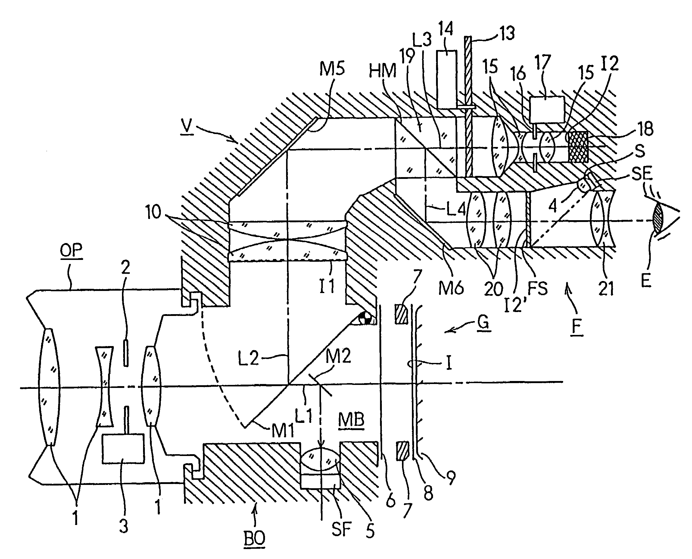
A camera divides a light beam having passed through a taking lens unit into two light beams. One light beam forms an image on a silver salt film. Another light beam forms an image on a CCD. A light path for said another light beam is provided with an aperture diaphragm. The taking lens unit has an aperture diaphragm. Said two aperture diaphragms are correlatively controlled by a controller incorporated in the camera.

Description

[0001]This application is a continuation of application Ser. No. 09 / 537,420 filed on Jan. 18, 2000, now abandoned, which is a continuation of application Ser. No. 09 / 232,821, filed on Jan. 19, 1999, now abandoned, which is a continuation of application Ser. No. 08 / 834,107 filed on Apr. 14, 1997, now U.S. Pat. No. 5,953,546, which is a continuation of application Ser. No. 08 / 659,690, filed Jun. 6, 1996, now U.S. Pat. No. 5,664,243.BACKGROUND OF THE INVENTION[0002]1. Field of the Invention[0003]The present invention relates to a camera in which an incident optical beam is divided for use in both photographing and observation of an image.[0004]2. Description of the Prior Art[0005]As a conventional example, an article in the June, 1994 issue of the “Photographic Industries” magazine, pages 12 to 15, describes a camera which is capable of changing the path of an incident light beam for the purpose of photographing and observing an image at the same time. According to the article, the cam...

Claims


Application Information

Patent Timeline
Patent Type & Authority Patents(United States)
IPC IPC(8): G03B13/02
CPCG03B13/02G03B17/02G03B17/17G03B17/20G03B19/06H04N5/225H04N5/238H04N23/75H04N23/00
Inventor NAGATA, HIDEKIHONDA, TSUTOMU
Owner MINOLTA CO LTD
Learn More